
Last Updated May 28, 2026
A solar-powered Arduino charger demonstrates how small renewable energy systems can generate, store, regulate, monitor, and distribute electricity at the edge of the grid. Large-scale energy infrastructure remains essential for modern societies, but small renewable systems also play an important role in expanding energy access, improving resilience, powering field electronics, and making clean-energy systems understandable through hands-on engineering.
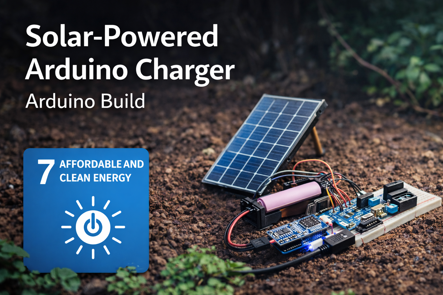
A solar-powered Arduino charging system combines a photovoltaic panel, rechargeable lithium-ion battery, charging module, boost converter, voltage divider, and Arduino-based monitoring circuit. Together, those components show how sunlight can be captured during the day, stored in a battery, regulated to a usable output voltage, and monitored so the user can understand battery condition and system behavior.
This project is not a substitute for grid infrastructure, certified consumer chargers, or professionally engineered solar power systems. Its value is educational and methodological. It makes the basic architecture of decentralized renewable energy visible: generation, storage, regulation, measurement, load support, safety, calibration, and responsible deployment.
Main Library
Publications
Project Series
Arduino SDG Projects
Related Topic
Infrastructure Systems
Related Topic
Environmental Monitoring
Related Topic
Climate Change
This project also connects to broader site areas, including Intelligent Infrastructure Systems, Environmental Monitoring Systems, Sustainable Development Goals Within Planetary Boundaries, Climate Change as a Planetary Boundary, and Planetary Boundaries. In that wider context, this solar charger is not only a maker project. It is a small prototype of the generation, storage, regulation, and monitoring infrastructure needed for cleaner, more resilient energy systems.
Abstract
This project presents a prototype solar-powered Arduino charger built around a small photovoltaic panel, lithium-ion battery, TP4056 charging module, boost converter, voltage divider, and Arduino-based voltage monitoring circuit. The system captures solar energy, stores it in a rechargeable cell, regulates output power, and reports battery status through serial telemetry and optional LED indicators.
From an engineering perspective, the build demonstrates a compact renewable power system with generation, storage, regulation, monitoring, and status-reporting layers. From a sustainability perspective, it illustrates how decentralized clean-energy systems can support energy access, resilience, field monitoring, emergency preparedness, and practical education around renewable infrastructure.
The project is intentionally small, but the design pattern matters. Solar energy systems are not only panels. They are systems of conversion, storage, regulation, protection, measurement, load management, and interpretation. This article treats the charger as a technical sustainability prototype rather than a simple electronics build.
SDG Alignment: Energy Access, Infrastructure, Resilience, Climate, and Responsible Use
This solar-powered Arduino charger connects most directly to SDG 7: Affordable and Clean Energy, especially the broader challenge of expanding access to reliable, sustainable, and modern energy. Although this project operates at prototype scale, it demonstrates a principle that matters at much larger scales: energy systems become more useful and resilient when generation, storage, regulation, and monitoring are designed together.
The project is not a complete energy-access solution, a certified consumer charger, or a substitute for safe electrical infrastructure. Its value is educational and methodological. It shows how a small embedded system can capture solar energy, store it in a battery, regulate voltage for useful loads, monitor battery condition, and communicate system status. That architecture is central to decentralized energy systems, off-grid sensing, disaster-resilient infrastructure, and renewable-energy literacy.
| Sustainable Development Goal | How the Project Relates | Project-Level Mechanism |
|---|---|---|
| SDG 7: Affordable and Clean Energy | Demonstrates small-scale renewable electricity generation, storage, and regulated power output. | Solar panel, lithium battery, charge controller, boost converter, and Arduino-based voltage monitoring. |
| SDG 9: Industry, Innovation and Infrastructure | Supports innovation through low-cost clean-energy prototyping and embedded monitoring. | Modular power-flow architecture, battery telemetry, reproducible firmware, and documented prototype design. |
| SDG 11: Sustainable Cities and Communities | Relates to local resilience, emergency preparedness, and small distributed power systems. | Portable renewable charging, off-grid support for small electronics, and local energy visibility. |
| SDG 12: Responsible Consumption and Production | Encourages more visible and repairable energy use while teaching battery awareness and system limits. | Voltage monitoring, status classification, calibration, load awareness, and reusable open documentation. |
| SDG 13: Climate Action | Connects to climate mitigation and adaptation by making low-carbon energy generation tangible. | Photovoltaic generation, battery storage, efficiency awareness, and support for low-power field systems. |
The strongest SDG connection is SDG 7. Energy access is not only a question of generation capacity. It also depends on storage, reliability, regulation, safety, and the ability to understand system state. A solar panel alone does not create a complete charging system. The battery, charge controller, boost converter, wiring, monitoring circuit, and load behavior all determine whether the system is useful and safe.
The connection to SDG 9 comes through infrastructure and innovation. This project is a small infrastructure prototype. It combines a renewable energy source, storage element, voltage-regulation pathway, monitoring layer, firmware, documentation, and reproducible project repository. That matters because sustainable infrastructure includes not only large-scale grids and utility systems, but also smaller distributed devices that can support field sensors, classrooms, remote experiments, local resilience, and early-stage engineering research.
The connection to SDG 11 should be framed through resilience rather than overclaiming. This prototype does not make a city sustainable by itself. It does, however, demonstrate a pattern that can matter in emergencies, community labs, field stations, and low-resource settings: small renewable systems can keep essential low-power devices operating when centralized power is unavailable, unreliable, or too expensive for the task.
The connection to SDG 12 comes through responsible energy use and repairable design. A charger that exposes battery voltage, status thresholds, and system behavior teaches users to notice the limits of storage and the cost of loads. It shifts the project from invisible consumption toward observable energy behavior. That is a useful sustainability lesson: responsible consumption improves when users can see how systems perform, where energy comes from, and when loads exceed available supply.
The connection to SDG 13 is indirect but meaningful. A small solar charger does not solve climate change. It does, however, make the physical logic of low-carbon electricity concrete. It shows that climate action depends not only on policy commitments, but also on the practical redesign of energy systems: generating electricity without combustion, storing it safely, regulating it efficiently, monitoring system health, and matching demand to available renewable supply.
Because the Sustainable Development Goals are broad public frameworks, it is important not to overclaim. This project is not a certified renewable-energy device, not a commercial power bank, not a grid-replacement technology, and not a complete energy-access intervention. Its contribution is narrower and still valuable: it teaches the technical architecture behind small renewable power systems. It turns SDG language into a concrete engineering sequence: capture sunlight, regulate charging, store energy, boost voltage, monitor battery condition, classify state, protect the system, and understand the limits of the load.
In that sense, the project works best as a bridge between sustainability language and engineering practice. It makes clean energy visible as a system rather than a slogan. It helps readers see that renewable energy requires design choices, measurement, safety, calibration, and responsible deployment.
Connections to Other Site Areas
This solar-powered Arduino charger belongs to a wider body of work on clean energy, sensing, and resilient infrastructure. It connects directly to Intelligent Infrastructure Systems because decentralized energy systems increasingly depend on monitoring, status feedback, voltage regulation, storage management, and safe control logic.
It also connects to Environmental Monitoring Systems. Many field sensors, water-quality stations, air-quality monitors, wildlife telemetry devices, and remote monitoring platforms require reliable power in locations where grid access is unavailable. A small solar charger demonstrates how monitoring systems can become more self-sufficient.
At the planetary-boundary level, the project relates most directly to Climate Change as a Planetary Boundary. Clean-energy systems are central to reducing fossil-fuel dependence and decarbonizing the energy systems that shape climate risk.
The project also supports the broader development logic explored in Sustainable Development Goals Within Planetary Boundaries. Energy access matters, but energy systems must be designed in ways that reduce emissions, improve resilience, and respect planetary limits.
System Architecture
The prototype can be understood as a compact renewable power system with five functional layers:
- Generation layer: a small photovoltaic panel converts sunlight into electrical energy.
- Charge-control layer: a TP4056 module regulates battery charging and, when equipped with protection circuitry, helps reduce some battery-related risks.
- Storage layer: a lithium-ion battery stores energy for later use.
- Regulation layer: a boost converter raises battery voltage to a stable 5V output for small devices or embedded loads.
- Monitoring layer: an Arduino reads scaled battery voltage through a voltage divider and reports system state.
The basic power-flow architecture is:
Solar Panel → Charge Controller → Battery → Boost Converter → 5V Output → LoadWith monitoring added, the system also includes a measurement path:
Battery → Voltage Divider → Arduino ADC → Battery Status / TelemetryThis architecture mirrors the structure of larger renewable energy systems in simplified form. Energy is generated, stored, conditioned, delivered, and monitored. The project’s educational value comes from making each stage visible.
System Requirements
A solar charger prototype becomes more useful when its requirements are stated clearly. The table below turns the project from a simple wiring exercise into a small renewable-energy system with measurable design expectations.
| Requirement | Design Target | Reason |
|---|---|---|
| Solar input | Capture energy from a small photovoltaic panel | Demonstrates renewable generation at prototype scale |
| Charge control | Use a lithium charging module with protection circuitry where possible | Reduces unsafe direct charging behavior and teaches battery-management principles |
| Energy storage | Store energy in a rechargeable lithium-ion cell | Supports operation when sunlight is unavailable or variable |
| Voltage regulation | Boost output to approximately 5V | Makes stored energy usable for USB-style loads and small embedded systems |
| Voltage monitoring | Measure scaled battery voltage through a divider | Supports status reporting, calibration, and safe interpretation of battery state |
| Telemetry | Print voltage and battery status to the Serial Monitor | Supports debugging, learning, and system evaluation |
| Safety | Verify polarity, voltage, heat, enclosure, and load behavior | Reduces risk from lithium cells, incorrect wiring, and unstable power conversion |
| Deployment scope | Use as an educational or prototype system | Clarifies that the project is not a certified consumer charger or production solar system |
These requirements can be reused across the rest of the Arduino sustainability project series. Each article should make the engineering target visible before moving into code or build steps.
Why a Solar-Powered Arduino Charger Matters
Most electronic devices depend on stable power supplies. In many parts of the world, electricity still comes from centralized power grids that rely heavily on fossil fuels, while some communities, field sites, and emergency settings face unreliable access to power altogether.
Solar power changes the equation by enabling energy generation directly at the point of use. Even small solar systems can support useful tasks such as charging phones, powering environmental sensors, running embedded systems, or keeping low-power monitoring stations alive in the field.
This Arduino-based prototype demonstrates four key principles of renewable energy systems:
- capture energy from sunlight using photovoltaic panels
- store electricity in rechargeable batteries
- regulate voltage so electronics can safely use stored energy
- monitor system state so the user can understand battery condition and system performance
Together, those components form a simple renewable energy system that is useful both as a hands-on build and as a teaching tool for sustainable development.
What This Project Does
This solar-powered Arduino system:
- captures solar energy using a small photovoltaic panel
- stores energy in a lithium-ion battery
- uses a charging module to regulate battery charging
- boosts voltage to provide a stable 5V output
- monitors battery voltage using Arduino
- reports battery state as full, normal, low, or critical
- can be extended with LEDs, LCDs, data logging, or wireless telemetry
In practical terms, the device functions as a small renewable charging station and a solar-energy monitoring prototype.
Parts List
- Arduino Nano or Arduino Uno
- 6V–9V solar panel
- 18650 lithium-ion battery
- TP4056 lithium battery charging module with protection circuitry
- DC boost converter set to 5V output
- USB output module or USB breakout
- two resistors for a voltage divider, such as 100kΩ and 100kΩ
- breadboard or small PCB
- jumper wires
- optional LEDs for status indication
- optional 16×2 LCD or OLED display
- project enclosure for safer handling and outdoor protection
For field-like testing, an enclosure, strain relief, clear polarity labels, insulated terminals, and a stable mounting surface are strongly recommended. The prototype should not be left outdoors or exposed to moisture unless enclosure and thermal behavior have been validated.
Engineering Specifications
| Parameter | Reference Specification |
|---|---|
| Microcontroller | Arduino Nano, Arduino Uno, or compatible 5V Arduino board |
| Solar input | Small 6V–9V photovoltaic panel, sized for prototype charging |
| Battery type | Single-cell lithium-ion battery, such as 18650 format |
| Charge module | TP4056 lithium charger, preferably with protection circuitry |
| Output regulator | DC boost converter set to approximately 5V |
| Voltage measurement | Battery voltage scaled through resistor divider into Arduino A0 |
| ADC resolution | 10-bit, 0–1023 on typical Arduino Uno/Nano boards |
| Monitoring interval | 5 seconds in the reference code |
| Status categories | Full, normal, low, critical |
| Deployment scope | Classroom, lab, makerspace, or controlled prototype environment |
Safety Notes Before You Begin
This project uses lithium-ion batteries, which must be handled carefully. A few important precautions:
- Use a TP4056 charging module with protection circuitry whenever possible.
- Do not connect a lithium battery directly to a solar panel without a charging controller.
- Do not exceed the charging module’s input limits.
- Verify the boost converter output with a multimeter before connecting any device.
- Do not short the battery terminals.
- Do not use damaged, swollen, overheated, or unknown lithium-ion cells.
- Do not leave the system exposed to rain, condensation, or high heat unless it is properly enclosed.
- Do not treat this prototype as a certified consumer charger.
This is an educational prototype, not a commercial power bank or certified solar charging product. Battery protection, enclosure design, fusing, thermal behavior, and safe charging limits matter in any practical energy-storage system.
Any system involving lithium batteries should be tested under observation first. Stop using the system immediately if the battery becomes hot, swollen, physically damaged, or unstable under load.
How the System Works
The solar panel converts sunlight into electrical current. That current flows into a charging module, which regulates the energy before it reaches the battery.
The lithium battery stores electricity during the day. When power is needed, the boost converter raises the battery voltage to a stable 5V output suitable for USB devices and small embedded systems.
An Arduino can optionally monitor battery voltage and report system status through the Serial Monitor, LED indicators, an LCD display, or a wireless dashboard.
The system should be understood as a controlled power path with a separate monitoring path. The power path moves energy from panel to charger to battery to output. The monitoring path samples battery voltage safely through a voltage divider so the Arduino can classify battery condition without exposing the analog pin to unsafe voltage.
Mathematical Lens: Voltage, Power, Energy, and State Monitoring
The solar charger can be understood through a few practical engineering equations. These equations do not make the prototype a full photovoltaic design tool, but they clarify how voltage measurement, power flow, battery energy, and output runtime are connected.
V_{A0}=V_{bat}\frac{R_2}{R_1+R_2}
\]
Interpretation: A voltage divider reduces battery voltage before it reaches the Arduino analog input.
Here, \(V_{A0}\) is the voltage seen by the Arduino analog pin, \(V_{bat}\) is the battery voltage, and \(R_1\) and \(R_2\) are the divider resistors. If the two resistors are equal, the analog input receives approximately half the battery voltage.
V_{bat}=V_{A0}\frac{R_1+R_2}{R_2}
\]
Interpretation: The firmware reverses the divider calculation to estimate actual battery voltage.
This is why the code includes a voltage-divider ratio. The Arduino measures the scaled voltage, then multiplies by the divider ratio to estimate the original battery voltage.
P=VI
\]
Interpretation: Electrical power equals voltage multiplied by current.
This relationship is central to solar charging. A higher voltage does not automatically mean useful power unless current is also available. In future upgrades, measuring both voltage and current would allow the project to estimate actual power flow.
E=P\times t
\]
Interpretation: Energy equals power multiplied by time.
This equation connects solar charging to runtime. A battery-powered device depends not only on instantaneous voltage but on how much energy has been stored and how quickly the load consumes it.
\eta=\frac{P_{out}}{P_{in}}
\]
Interpretation: Conversion efficiency compares useful output power to input power.
The boost converter does not transfer energy perfectly. Some energy is lost as heat. Understanding efficiency helps explain why battery capacity, solar-panel size, converter choice, and load behavior all matter.
The mathematical lens shows that this project is not simply “solar panel plus battery.” It is a measurement and energy-conversion system. It depends on scaling voltage safely, interpreting analog readings, regulating power, estimating system state, and respecting the physical limits of generation, storage, and load demand.
Circuit Logic and Power Flow
The circuit has two related but distinct functions: moving power and measuring system state. The power circuit handles energy conversion and delivery. The monitoring circuit lets the Arduino observe battery voltage without becoming part of the main charging pathway.
The solar panel should feed the charging module, not the battery directly. The battery should feed the boost converter, which provides regulated 5V output to small devices. The Arduino monitoring input should be connected only through a safe voltage divider.
This separation matters because power electronics behave differently from logic electronics. Solar panels vary with sunlight, angle, temperature, and load. Lithium batteries have safe voltage ranges and charging constraints. Boost converters create switching behavior and may become inefficient or unstable under certain loads. Arduino analog inputs are designed for measurement, not for raw power handling.
For a more robust future version, the circuit could include fusing, reverse-polarity protection, current sensing, thermal monitoring, enclosure sealing, better connectors, and load cutoff. The introductory version remains useful because it teaches the most important system distinction: energy should move through the power path, while information should move through the measurement path.
Basic Wiring Overview
Solar Charging Circuit
- Solar Panel + → TP4056 IN+
- Solar Panel – → TP4056 IN–
- Battery + → TP4056 B+
- Battery – → TP4056 B–
Power Output Circuit
- TP4056 OUT+ → Boost Converter IN+
- TP4056 OUT– → Boost Converter IN–
- Boost Converter OUT+ → USB 5V
- Boost Converter OUT– → USB GND
Arduino Monitoring Circuit
- Battery positive line → voltage divider → Arduino A0
- Battery ground → Arduino GND
Important: the Arduino analog pin should never receive the full raw battery or panel voltage unless it is safely scaled down through a voltage divider. Always verify the divider output with a multimeter before connecting it to the Arduino analog input.
Voltage Divider Example
If you use two equal resistors, such as 100kΩ and 100kΩ, the voltage divider cuts the battery voltage in half before it reaches A0. That means a 4.2V battery will appear as approximately 2.1V to the Arduino, which is safe for a 5V Arduino analog input.
For a 2:1 voltage divider:
- Battery positive → resistor 1 → analog pin
- Analog pin → resistor 2 → ground
The code below assumes a divider ratio of 2.0. Adjust that value if your resistor values differ. For more precise readings, measure the actual resistor values with a multimeter and calculate the real divider ratio.
Firmware Design Goals
The firmware should do more than report a raw analog value. A useful solar-charger monitor should:
- read battery voltage through a safe voltage divider
- average multiple analog samples for stability
- convert analog readings into estimated battery voltage
- classify battery state in plain language
- drive optional LED indicators for quick physical feedback
- provide readable serial output for diagnostics
These design goals make the system easier to test, easier to calibrate, and easier to extend later with displays, logging, or wireless telemetry.
Basic vs. Advanced Firmware
A minimal version of this project could read one analog value and print it to the Serial Monitor. That is enough to prove the circuit works, but it is not enough to teach reliable monitoring. A single noisy reading may mislead the user, and a raw analog value does not communicate battery condition clearly.
The advanced version used here averages multiple samples, converts ADC readings into estimated battery voltage, classifies battery condition, prints human-readable telemetry, and controls optional LED indicators. Those additions make the prototype more useful without making the system inaccessible.
This distinction should guide the rest of the Arduino sustainability project series: the goal is not unnecessary complexity, but enough engineering structure to make measurement, calibration, interpretation, and responsible use visible.
Arduino Code: Advanced Monitoring Sketch
The following sketch goes beyond a simple analog read. It averages samples, converts them into estimated battery voltage, classifies battery state, and drives optional LEDs that indicate system condition.
/*
  Solar-Powered Arduino Charger Monitor

  Features:
  - Reads battery voltage through a voltage divider
  - Averages multiple analog samples for more stable readings
  - Converts raw ADC readings into estimated battery voltage
  - Reports battery state: FULL, NORMAL, LOW, or CRITICAL
  - Drives optional LED status indicators
  - Prints serial output for diagnostics

  Safety notes:
  - Use a lithium charging module with protection circuitry.
  - Do not connect lithium batteries directly to a solar panel.
  - Verify boost converter output before connecting devices.
  - This is an educational prototype, not a certified consumer charger.
*/

// Analog input for scaled battery voltage.
const int batteryPin = A0;

// Optional LED status pins.
const int ledFullPin = 4;
const int ledNormalPin = 5;
const int ledLowPin = 6;
const int ledCriticalPin = 7;

// Arduino ADC reference voltage.
// Measure your board's real 5V rail and adjust if needed.
const float referenceVoltage = 5.0;

// Voltage divider ratio.
// With two equal resistors, the battery voltage is divided by 2,
// so the measured analog voltage must be multiplied by 2.
const float voltageDividerRatio = 2.0;

// Battery thresholds for one lithium-ion cell.
// Adjust based on the cell, load, protection board, and safety requirements.
const float batteryFull = 4.15;
const float batteryNormalMin = 3.70;
const float batteryLow = 3.40;
const float batteryCritical = 3.20;

// Number of analog samples used for averaging.
const int sampleCount = 20;

// Delay between monitoring updates.
const unsigned long sampleDelayMs = 5000;

float readBatteryVoltage() {
  /*
    Average multiple ADC readings to reduce noise.

    The Arduino analog-to-digital converter returns values from 0 to 1023.
    Convert the averaged raw value into voltage at A0, then multiply by
    the voltage divider ratio to estimate true battery voltage.
  */
  long total = 0;

  for (int i = 0; i < sampleCount; i++) {
    total += analogRead(batteryPin);
    delay(10);
  }

  float averageRaw = total / (float)sampleCount;
  float measuredVoltage = averageRaw * (referenceVoltage / 1023.0);
  float batteryVoltage = measuredVoltage * voltageDividerRatio;

  return batteryVoltage;
}

void clearLeds() {
  // Turn off all status LEDs before setting the current state.
  digitalWrite(ledFullPin, LOW);
  digitalWrite(ledNormalPin, LOW);
  digitalWrite(ledLowPin, LOW);
  digitalWrite(ledCriticalPin, LOW);
}

const char* batteryStatusLabel(float voltage) {
  // Classify battery condition using simple voltage thresholds.
  if (voltage >= batteryFull) {
    return "FULL";
  } else if (voltage >= batteryNormalMin) {
    return "NORMAL";
  } else if (voltage >= batteryLow) {
    return "LOW";
  } else {
    return "CRITICAL";
  }
}

void setBatteryStatusLeds(float voltage) {
  // Display battery state using optional LEDs.
  clearLeds();

  if (voltage >= batteryFull) {
    digitalWrite(ledFullPin, HIGH);
  } else if (voltage >= batteryNormalMin) {
    digitalWrite(ledNormalPin, HIGH);
  } else if (voltage >= batteryLow) {
    digitalWrite(ledLowPin, HIGH);
  } else {
    digitalWrite(ledCriticalPin, HIGH);
  }
}

void printBatteryAdvisory(float voltage) {
  // Print human-readable advisory messages for the Serial Monitor.
  if (voltage >= batteryFull) {
    Serial.println("Battery is near full charge.");
  } else if (voltage >= batteryNormalMin) {
    Serial.println("Battery is in a healthy operating range.");
  } else if (voltage >= batteryLow) {
    Serial.println("Battery is getting low. Charging recommended.");
  } else {
    Serial.println("Battery is critical. Reduce load and recharge immediately.");
  }
}

void setup() {
  // Start serial diagnostics.
  Serial.begin(9600);

  // Configure optional LED pins.
  pinMode(ledFullPin, OUTPUT);
  pinMode(ledNormalPin, OUTPUT);
  pinMode(ledLowPin, OUTPUT);
  pinMode(ledCriticalPin, OUTPUT);

  clearLeds();

  Serial.println("Solar-Powered Arduino Charger Monitor");
  Serial.println("-------------------------------------");
  Serial.println("Reading battery voltage...");
}

void loop() {
  // Read estimated battery voltage.
  float batteryVoltage = readBatteryVoltage();

  // Classify battery state.
  const char* status = batteryStatusLabel(batteryVoltage);

  // Update optional LEDs.
  setBatteryStatusLeds(batteryVoltage);

  // Print readable telemetry.
  Serial.print("Battery Voltage: ");
  Serial.print(batteryVoltage, 2);
  Serial.print(" V | Status: ");
  Serial.println(status);

  printBatteryAdvisory(batteryVoltage);

  Serial.println();

  delay(sampleDelayMs);
}GitHub Repository
The article body includes the core firmware and design explanation so the build remains readable. The full repository expands the project into a reproducible prototype package, including Arduino monitoring firmware, setup documentation, calibration notes, bill of materials, example battery-voltage readings, and wiring and power-flow materials.
Complete Code Repository
The full code distribution for this project, including Arduino monitoring firmware, setup documentation, calibration notes, bill of materials, example battery-voltage readings, and wiring and power-flow materials, is available on GitHub.
The repository contains the complete prototype build materials:
- Arduino monitoring firmware
- bill of materials
- setup guide
- calibration notes
- example battery-voltage readings
- wiring and power-flow diagrams
Repository Structure
solar-arduino-charger/

README.md
LICENSE

BOM.csv

firmware/
  solar_charger_monitor.ino

docs/
  setup_guide.md
  calibration.md
  deployment_notes.md
  power_flow.md

data/
  example_battery_voltage_readings.csv

hardware/
Engineers can clone the repository, fork the design, or download the complete project using GitHub’s Download ZIP feature. All materials are released under the MIT License to support reuse in research, education, and prototype engineering work.
Code Review and Engineering Notes
A few technical details are worth noting:
- Averaging: the
readBatteryVoltage()function averages multiple analog samples to reduce short-term noise. - Voltage conversion: the code converts ADC readings into measured analog voltage and then estimates battery voltage using the divider ratio.
- Status thresholds: the sketch classifies the battery as full, normal, low, or critical using simple voltage thresholds.
- LED feedback: optional LEDs make system state visible without a computer.
- Calibration dependency: accurate voltage reporting depends on the real Arduino reference voltage and actual resistor values.
- Blocking delay: the reference code is intentionally simple, but future versions could replace delays with a fully non-blocking scheduler.
The firmware is therefore best read as a stable educational reference implementation. It is more robust than a one-line analog-read demonstration, but still simple enough to teach voltage measurement, threshold classification, and renewable-energy monitoring.
Failure Modes and Practical Risks
A useful sustainability prototype should explain not only how the system works, but also how it can fail. Solar chargers operate in variable physical conditions: sunlight changes, batteries age, loads fluctuate, converters heat up, wiring loosens, and measurement circuits drift. The most important failure modes are predictable.
- Incorrect polarity: reversed battery, panel, or module connections can damage components or create safety hazards.
- Unsafe lithium charging: connecting a battery directly to a solar panel or using an unprotected cell can create serious risk.
- Overvoltage at A0: an incorrect voltage divider can expose the Arduino analog input to unsafe voltage.
- Boost converter misadjustment: an output set above 5V can damage connected USB devices or microcontrollers.
- Battery overdischarge: continued load use below safe voltage can damage lithium cells.
- Thermal stress: chargers, converters, and batteries may heat under load or direct sun.
- Weather exposure: rain, condensation, dust, and heat can degrade exposed electronics.
- False confidence: a voltage-only monitor may appear more informative than it is if current, temperature, and battery health are not measured.
- Load mismatch: a load may require more current than the panel, battery, or converter can safely provide.
- Connector failure: loose breadboard connections can create intermittent behavior that looks like software error.
These risks do not make the project unusable. They make testing essential. A responsible prototype should be checked with a multimeter, observed during first operation, tested under realistic loads, and kept within safe battery and converter limits.
Practical Calibration Notes
Battery voltage readings are only as good as the calibration process. A few things to verify:
- Make sure your Arduino reference voltage is actually close to 5.0V.
- Check your resistor values with a multimeter if possible.
- Confirm the voltage divider ratio in code.
- Compare the Arduino reading to an external multimeter reading and fine-tune if needed.
- Test readings across several battery levels rather than relying on one point.
If your system consistently reads too high or too low, adjust the referenceVoltage or voltageDividerRatio values in the code.
Example Calibration Record
| Condition | Multimeter Voltage | Arduino Estimate | Difference | Adjustment Needed? |
|---|---|---|---|---|
| Battery near full | 4.12 V | 4.18 V | +0.06 V | Possibly reduce divider ratio or reference voltage |
| Battery normal | 3.82 V | 3.86 V | +0.04 V | Minor adjustment optional |
| Battery low | 3.42 V | 3.47 V | +0.05 V | Check threshold sensitivity |
A calibration record like this gives the voltage estimate a reason. Instead of trusting code defaults, the builder compares the Arduino reading against an external reference and tunes the calculation for the actual circuit.
Validation and Testing
To bring this project closer to engineering-grade documentation, validation matters. A simple testing procedure should include:
- verify all polarity before inserting the battery
- measure solar panel output in sun and shade
- confirm that the charging module behaves as expected
- measure boost converter output before attaching a load
- compare Arduino voltage estimates against a multimeter
- test the system with a small known load
- observe temperature of the battery, charger, and converter during operation
- confirm that low and critical battery states trigger appropriate warnings
If the system performs poorly, the problem may not be code. It may be weak sunlight, undersized panel capacity, poor battery health, converter inefficiency, loose wiring, inaccurate resistor values, or a load that exceeds the system’s capability.
A useful validation test is to log battery voltage at regular intervals in bright sun, partial shade, and under load. This helps reveal whether the charger is actually increasing stored energy or merely maintaining a weak voltage signal without enough current to support meaningful use.
Suggested Performance Metrics
For a more rigorous evaluation, the charger can be assessed using several simple metrics:
- Battery voltage accuracy: agreement between Arduino estimate and multimeter reading.
- Charging response: whether voltage rises under sunlight and stabilizes under shade or load.
- Output stability: whether the boost converter maintains approximately 5V output.
- Load runtime: how long the system can power a small device or embedded load.
- Status classification: whether full, normal, low, and critical states match expected battery behavior.
- Thermal behavior: whether battery, charger, and converter remain within safe operating conditions.
- Recovery time: how long the system takes to recover voltage after load removal or sunlight exposure.
Even informal tracking of these metrics improves the technical credibility and educational value of the project. The goal is not laboratory-grade photovoltaic characterization; it is disciplined observation of how a small renewable power system behaves.
Data Logging Extension
The charger becomes more useful when battery voltage, sunlight condition, output status, and load behavior are logged over time. Even a simple CSV file can help evaluate whether the charger is gaining energy in sunlight, losing energy under load, or behaving differently under cloudy or indoor conditions.
| Field | Example | Purpose |
|---|---|---|
| timestamp | 2026-05-28 14:30:00 | Records when the measurement occurred |
| battery_voltage | 3.84 | Estimated battery voltage from Arduino ADC |
| status | NORMAL | Plain-language battery state |
| solar_condition | bright sun | Context for interpreting charging behavior |
| load_connected | yes | Documents whether the output was powering a device |
| output_voltage | 5.03 | Measured boost converter output, if logged manually or with additional sensing |
| notes | panel partly shaded | Captures environmental or testing context |
For a more advanced version, an SD card module, ESP32, or wireless telemetry system could store and transmit these values. The important point is methodological: logging transforms the project from a one-time demonstration into an interpretable renewable-energy dataset.
Optional Upgrade: Add LED Status Indicators
If you wire LEDs to pins 4–7 with appropriate current-limiting resistors, the system can show battery state at a glance:
- Pin 4 — FULL
- Pin 5 — NORMAL
- Pin 6 — LOW
- Pin 7 — CRITICAL
This makes the build more practical in field or classroom use, especially if no laptop is attached. A future version could replace LEDs with an OLED display, LCD, buzzer alert, or wireless dashboard.
Build Steps
1. Connect the Solar Panel
Attach the solar panel leads to the input terminals of the TP4056 lithium charging module. Confirm polarity before exposing the panel to strong sunlight.
2. Install the Battery
Connect the lithium-ion battery to the module’s battery terminals. Double-check polarity before powering the system.
3. Add the Boost Converter
Connect the TP4056 output to the boost converter input. Before attaching any USB device, use a multimeter to verify that the boost converter is set to approximately 5V output.
4. Build the Voltage Divider
Add the resistor divider between the battery positive line and ground, with the midpoint connected to Arduino A0.
5. Upload the Monitoring Sketch
Upload the advanced monitoring sketch and open the Serial Monitor at 9600 baud.
6. Test Charging Behavior
Place the solar panel in sunlight and observe how the measured battery voltage changes. Compare charging behavior in bright sun, shade, and indoor light.
7. Add LEDs or a Display
Once the basic system works, add LED indicators or a display to make the charger easier to read without a laptop.
8. Record Calibration and Test Results
Document multimeter readings, Arduino estimates, sunlight conditions, output voltage, and load behavior. This makes future tuning easier and improves reproducibility.
Limitations
This project is an educational prototype rather than a production solar energy system.
Limitations include:
- small solar panel output
- limited battery storage capacity
- weather-dependent generation
- basic voltage-based monitoring rather than full power analytics
- no current monitoring in the baseline design
- no certified enclosure, thermal management, or consumer charging safety certification
- no maximum power point tracking
- no automated load cutoff in the baseline design
- no battery temperature measurement unless added as an upgrade
Despite these limitations, the system effectively demonstrates the core principles behind renewable energy infrastructure: generation, storage, regulation, monitoring, and load support.
Possible Upgrades
Add Energy Monitoring
Measure both solar input and output current to estimate actual power flow, charging efficiency, and load behavior.
Add Data Logging
An SD card module can record battery voltage and solar production over time.
Add Wi-Fi Connectivity
An ESP32 could transmit solar production data to a local or cloud dashboard.
Add a Display
A 16×2 LCD or OLED can turn the charger into a standalone monitoring device.
Increase Solar Capacity
Larger panels and additional batteries can expand system capability and improve practical usefulness.
Add Load Switching
A MOSFET or relay could automatically disconnect non-critical loads when battery voltage drops below a safe threshold.
Add Battery Temperature Monitoring
A temperature sensor near the battery can provide early warning if the enclosure or charging conditions become unsafe.
Add Current Sensing
A current sensor can help estimate real power flow, converter efficiency, and load demand.
Responsible Deployment
This prototype is appropriate for classrooms, labs, makerspaces, controlled demonstrations, field-methods education, and early-stage engineering experiments. It should not be used as a certified consumer charger, emergency power system, unattended outdoor device, or long-term field power supply without additional validation, protection, enclosure testing, thermal analysis, and load-control design.
Responsible deployment means matching the system to the consequence of failure. If a classroom LED status indicator is wrong, the consequence is modest. If the charger powers a remote environmental monitoring station, emergency communication device, or expensive sensor package, the design standard must be higher.
A responsible version should include battery protection, fusing, thermal monitoring, waterproof enclosure design, secure wiring, strain relief, load cutoff, calibration records, and a documented maintenance plan. The prototype teaches the core architecture, but deployment requires engineering discipline beyond the first successful test.
Why This Matters for Sustainable Development
Renewable energy is often discussed at the scale of national infrastructure, utility systems, and major capital investment. But the underlying technologies operate on the same basic principles whether they power a city, a field sensor, a classroom prototype, or a small emergency charging station.
Solar panels convert light into electricity. Batteries store that electricity. Control systems regulate how it is used. Monitoring systems help people understand whether the system is working safely and effectively.
Projects like this demonstrate those principles in accessible ways. A student building a solar charging system is learning not only electronics, but also the physical logic behind renewable energy systems, battery storage, distributed infrastructure, and energy resilience.
This solar-powered Arduino charger also shows why decentralized energy systems matter in policy terms: they can improve resilience, expand access, support field monitoring, and make sustainability tangible at small scales.
The project also shows why clean-energy technology should not be treated only as hardware. The real value comes from the relationship among generation, storage, regulation, measurement, safety, and responsible use. A solar panel does not automatically make a system sustainable. A well-designed energy pathway can help.
Reproducibility
All firmware, documentation, and supporting build materials necessary to reproduce the prototype are included in the project repository. The design intentionally relies on widely available educational and hobbyist hardware so that it can be rebuilt in classrooms, labs, makerspaces, field stations, and independent engineering environments.
The system is intended as a reference implementation rather than a certified consumer charger or production solar power system. Engineers adapting it for more demanding or longer-term use should validate battery safety, enclosure design, charge-controller behavior, boost-converter output, thermal performance, wiring reliability, and load compatibility under real operating conditions.
For the rest of this project series, reproducibility should mean more than making code available. Each article should include a clear bill of materials, wiring logic, calibration notes, failure modes, test procedure, data interpretation guidance, and a realistic statement of appropriate use.
Conclusion
A solar-powered Arduino charging system is a small project, but it demonstrates how renewable energy systems capture, store, regulate, monitor, and distribute electricity.
By combining a solar panel, lithium battery, voltage-regulation components, and Arduino-based monitoring, the build creates a portable power system that can support small electronics while making clean-energy behavior visible and measurable.
In educational settings, makerspaces, and sustainability research labs, projects like this help translate renewable energy concepts into practical experimentation. They make it possible to see energy not as an abstraction, but as a flow that must be generated, stored, regulated, measured, protected, and used responsibly.
The deeper lesson is not simply that an Arduino can monitor a battery. The deeper lesson is that sustainable energy systems require feedback. When renewable generation is connected to storage, regulation, measurement, safety, and responsible load management, even a small prototype can demonstrate the logic of cleaner and more resilient infrastructure.
Related Articles
- Arduino Projects for Sustainable Development: 10 SDG-Aligned Builds
- Smart Irrigation Controller with Arduino
- Intelligent Infrastructure Systems
- Environmental Monitoring Systems
- Sustainable Development Goals Within Planetary Boundaries
- Climate Change as a Planetary Boundary
- Planetary Boundaries
Further Reading
- Arduino (n.d.) analogRead(). Available at: https://docs.arduino.cc/language-reference/en/functions/analog-io/analogRead/
- Arduino (n.d.) Arduino Documentation. Available at: https://docs.arduino.cc/
- International Energy Agency (n.d.) Solar PV. Available at: https://www.iea.org/energy-system/renewables/solar-pv
- National Renewable Energy Laboratory (n.d.) Solar Research. Available at: https://www.nrel.gov/solar/
- United Nations (n.d.) Sustainable Development Goal 7: Affordable and Clean Energy. Available at: https://sdgs.un.org/goals/goal7
- United Nations (n.d.) Sustainable Development Goal 9: Industry, Innovation and Infrastructure. Available at: https://sdgs.un.org/goals/goal9
- United Nations (n.d.) Sustainable Development Goal 11: Sustainable Cities and Communities. Available at: https://sdgs.un.org/goals/goal11
- United Nations (n.d.) Sustainable Development Goal 12: Responsible Consumption and Production. Available at: https://sdgs.un.org/goals/goal12
- United Nations (n.d.) Sustainable Development Goal 13: Climate Action. Available at: https://sdgs.un.org/goals/goal13
References
- Arduino (n.d.) analogRead(). Available at: https://docs.arduino.cc/language-reference/en/functions/analog-io/analogRead/
- Arduino (n.d.) Arduino Documentation. Available at: https://docs.arduino.cc/
- International Energy Agency (n.d.) Solar PV. Available at: https://www.iea.org/energy-system/renewables/solar-pv
- National Renewable Energy Laboratory (n.d.) Solar Research. Available at: https://www.nrel.gov/solar/
- United Nations (n.d.) The 17 Sustainable Development Goals. Available at: https://sdgs.un.org/goals
- United Nations (n.d.) Sustainable Development Goal 7: Affordable and Clean Energy. Available at: https://sdgs.un.org/goals/goal7
- United Nations (n.d.) Sustainable Development Goal 9: Industry, Innovation and Infrastructure. Available at: https://sdgs.un.org/goals/goal9
- United Nations (n.d.) Sustainable Development Goal 11: Sustainable Cities and Communities. Available at: https://sdgs.un.org/goals/goal11
- United Nations (n.d.) Sustainable Development Goal 12: Responsible Consumption and Production. Available at: https://sdgs.un.org/goals/goal12
- United Nations (n.d.) Sustainable Development Goal 13: Climate Action. Available at: https://sdgs.un.org/goals/goal13