
Last Updated May 28, 2026
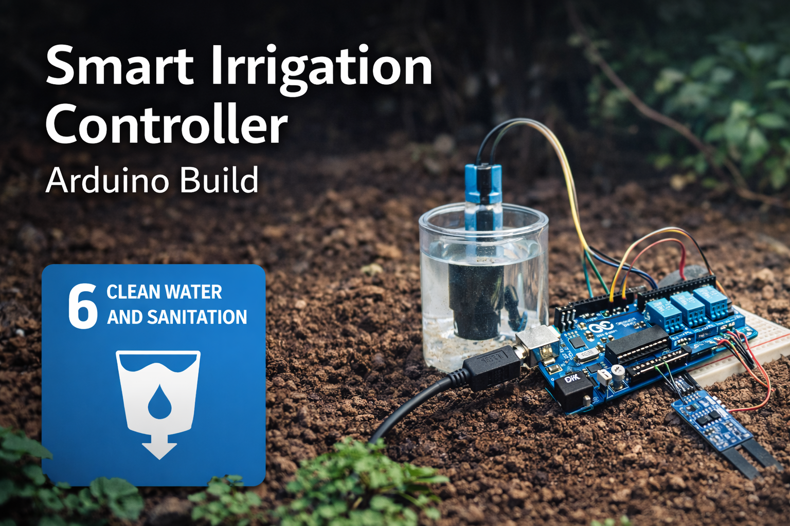
A smart irrigation controller with Arduino demonstrates how low-cost sensing can support more intelligent water management. Traditional irrigation systems often operate on fixed timers rather than real soil conditions. The result is familiar: overwatering, wasted energy, unnecessary pressure on freshwater resources, and, in some cases, reduced plant health.
A smart irrigation controller with Arduino replaces that assumption-based approach with measurement. By pairing an Arduino with a soil moisture sensor, relay module, and small pump, it becomes possible to water plants only when the soil actually needs it.
That may sound modest, but the underlying idea is important. Sustainable development often advances through systems that replace assumptions with observation. In water-constrained environments, better sensing can support more responsible freshwater use, more resilient growing systems, and more efficient small-scale infrastructure.
Main Library
Publications
Project Series
Arduino SDG Projects
Related Topic
Environmental Monitoring
Related Topic
Infrastructure Systems
Related Topic
Freshwater Risk
This project also connects to broader site areas, including Environmental Monitoring Systems, Intelligent Infrastructure Systems, Freshwater Change and Earth System Risk, Sustainable Development Goals Within Planetary Boundaries, Land-System Change and Ecological Transformation, and Planetary Boundaries. In that wider context, this irrigation controller is not only a maker project. It is a small prototype of the sensing, feedback, and control infrastructure needed for more water-efficient agriculture, gardening, and climate-adaptive resource management.
Abstract
This project presents a prototype smart irrigation controller built around an Arduino microcontroller, a capacitive soil moisture sensor, an optional DHT22 environmental sensor, a relay module, and a small pump. The controller measures soil conditions, compares the measured value to a calibrated dryness threshold, and activates irrigation only when the substrate is sufficiently dry.
From an engineering perspective, the project demonstrates a simple closed-loop control system with explicit sensing, decision, and actuation stages. From a sustainability perspective, it demonstrates how embedded sensing and automation can improve water-use efficiency in small-scale growing environments.
The project is intentionally modest, but the design pattern is important: environmental state is measured, interpreted, translated into control logic, and used to regulate resource use. That pattern appears throughout smart agriculture, environmental monitoring, water stewardship, climate-adaptive infrastructure, and low-cost sustainability instrumentation.
SDG Alignment
This smart irrigation controller with Arduino connects most directly to SDG 6: Clean Water and Sanitation, particularly the goal of improving water-use efficiency and supporting more sustainable freshwater management.
Related themes also appear in:
- SDG 2: Zero Hunger — through improved small-scale food production and more efficient growing systems.
- SDG 9: Industry, Innovation and Infrastructure — through low-cost sensing, control systems, and irrigation automation.
- SDG 12: Responsible Consumption and Production — by reducing unnecessary water use and supporting more efficient resource management.
- SDG 13: Climate Action — since water efficiency, drought adaptation, soil moisture, and energy use are closely linked.
Water management is increasingly recognized as a systemic sustainability challenge. Soil sensing, feedback control, and efficient irrigation can help small growing systems use water more carefully while demonstrating the same logic used in larger smart-agriculture and climate-adaptation systems.
Connections to Other Site Areas
This smart irrigation controller belongs to a wider body of work on sensing, infrastructure, and environmental feedback systems. It connects directly to Environmental Monitoring Systems because soil moisture, temperature, humidity, and irrigation timing are measurable environmental variables that can guide better decisions.
It also connects to Intelligent Infrastructure Systems. Irrigation systems become more intelligent when they can sense conditions, evaluate thresholds, activate pumps or valves, and record system behavior over time.
At the planetary-boundary level, this project relates to Freshwater Change and Earth System Risk. Local irrigation projects do not describe the entire freshwater boundary, but they demonstrate the same principle: water systems become more manageable when their physical conditions are observed and acted on carefully.
The project also connects to Land-System Change and Ecological Transformation because irrigation decisions influence soil conditions, plant health, garden productivity, and land-use practices. At small scale, smart irrigation shows how measurement and feedback can support more responsible interaction with land and water systems.
System Architecture
The prototype can be understood as a simple embedded sensing and actuation system consisting of four functional layers:
- Sensing layer: a capacitive soil moisture sensor measures dielectric changes associated with water content in the substrate.
- Environmental context layer: an optional DHT22 sensor measures temperature and relative humidity.
- Control layer: the Arduino reads sensor input, applies threshold logic, and manages irrigation timing.
- Actuation layer: a relay switches an external pump that delivers irrigation water.
The resulting control loop can be summarized as:
Soil Sensor → ADC → Arduino Control Logic → Relay → Pump → Soil Moisture Change → SensorThis pattern represents a minimal closed-loop environmental control system and illustrates how embedded sensing can support resource-efficient irrigation.
System Requirements
A smart irrigation prototype becomes more useful when its requirements are stated clearly. The table below turns the project from a simple wiring exercise into a small engineering system with measurable design expectations.
| Requirement | Design Target | Reason |
|---|---|---|
| Moisture sensing | Detect relative dry and wet soil conditions | Supports irrigation decisions based on measured substrate state |
| Pump control | Activate only after dryness threshold and lockout checks | Prevents unnecessary watering and rapid cycling |
| Power separation | Use an external pump supply | Protects the Arduino board from excessive current draw |
| Calibration | Record wet, dry, and threshold readings | Makes sensor interpretation specific to the actual soil and placement |
| Telemetry | Print readings and pump events to the Serial Monitor | Supports debugging, calibration, and learning |
| Lockout timing | Pause before the next watering cycle | Allows water to distribute through soil before the next decision |
| Safety | Keep electronics isolated from water | Reduces short-circuit, corrosion, and failure risk |
| Deployment scope | Use in controlled gardens, classrooms, greenhouses, or prototypes | Clarifies that this is not a certified agricultural or safety-critical system |
These requirements can be reused across the rest of the Arduino sustainability project series. Each article should make the engineering target visible before moving into code or build steps.
Why a Smart Irrigation Controller with Arduino Matters
Many irrigation systems operate using fixed timers. While timers are simple, they ignore real environmental conditions. Soil may already be wet from recent watering, evaporation may be low, rainfall may have occurred, or humidity may already be high enough that additional watering is unnecessary.
A smart irrigation controller introduces a basic feedback process:
- measure soil moisture
- compare it to a calibrated threshold
- activate irrigation only when soil is dry
- wait and measure again after water has distributed through the soil
This logic demonstrates a broader sustainability principle: better sensing enables better resource allocation. It also demonstrates a core engineering principle: systems become more efficient when control decisions are tied to measured state rather than assumption.
For a small garden, the immediate outcome may be less water waste and more consistent plant care. For sustainability education, the deeper value is conceptual: the project makes visible the relationship among measurement, uncertainty, control, resource use, and environmental responsibility.
What This Project Does
This Arduino smart irrigation controller:
- reads soil moisture from a capacitive sensor
- optionally reads humidity and temperature using a DHT22
- activates a relay-controlled water pump
- prevents excessive watering through lockout timing
- reports environmental data through the Serial Monitor
- supports calibration and threshold tuning
- creates a foundation for future logging, dashboarding, or multi-zone irrigation control
In practical terms, the system functions as a small automated irrigation controller suitable for experimentation, educational environments, greenhouse prototypes, container gardens, and early-stage water-efficiency projects.
Bill of Materials
- Arduino Uno or Arduino Nano
- capacitive soil moisture sensor
- DHT22 temperature and humidity sensor, optional but useful for context
- 5V relay module
- 5V submersible pump
- breadboard or terminal block arrangement
- jumper wires
- external 5V power supply for pump
- water reservoir
- optional irrigation tubing
- protective enclosure for electronics
For field-like testing, a waterproof electronics enclosure, strain relief for wires, drip loops, cable glands, and a physically stable pump mount are strongly recommended. The prototype should not be left unattended near water unless its electrical protection and enclosure design have been validated.
Engineering Specifications
| Parameter | Specification |
|---|---|
| Microcontroller | Arduino Uno, Arduino Nano, or equivalent ATmega328P-compatible board |
| Sensor type | Capacitive soil moisture sensor |
| ADC resolution | 10-bit, 0–1023 |
| Environmental sensor | DHT22, optional |
| Relay control voltage | 5V logic relay module |
| Pump supply | External 5V DC recommended |
| Sampling interval | 60 seconds in the reference code |
| Pump runtime | 3 seconds per cycle, configurable |
| Watering lockout interval | 5 minutes in the reference code |
| Deployment scope | Indoor greenhouse, container garden, classroom, or small garden prototype |
Measurement Principle: How the Soil Sensor Works
Capacitive soil moisture sensors do not directly measure “water” in a literal sense. Instead, they estimate moisture by measuring changes in the dielectric properties of the surrounding material.
Water has a much higher dielectric constant than dry soil. As soil becomes wetter, the electrical field around the sensor changes. The sensor electronics convert that change into an analog output that the Arduino can read.
This is an important engineering distinction: the sensor output is not a universal absolute moisture value. It is a context-dependent signal that must be calibrated for the soil, container geometry, sensor depth, soil salinity, temperature, and placement conditions in the specific system.
The measurement is therefore best understood as a relative indicator of substrate condition. The controller does not know the true volumetric water content of the soil unless the sensor has been calibrated against a reliable reference method. For this prototype, the practical goal is simpler: distinguish “dry enough to water” from “moist enough to wait” with acceptable repeatability for the intended use.
Mathematical Lens: From Sensor Reading to Irrigation Decision
The smart irrigation controller can be understood as a simple threshold-based control system. The Arduino reads an analog voltage from the soil moisture sensor, converts that signal into a 10-bit analog-to-digital value, smooths the measurement through averaging, and compares the result with a calibrated dryness threshold.
\bar{x}=\frac{1}{n}\sum_{i=1}^{n}x_i
\]
Interpretation: The controller averages \(n\) sensor readings to reduce short-term noise before making an irrigation decision.
If \(x_i\) represents one soil moisture sensor reading and \(n\) is the number of readings collected, then \(\bar{x}\) gives the smoothed value used by the controller.
I =
\begin{cases}
1, & \bar{x} > T_d \ \text{and lockout time has elapsed} \\
0, & \bar{x} \leq T_d \ \text{or lockout time has not elapsed}
\end{cases}
\]
Interpretation: Irrigation turns on only when the averaged soil reading exceeds the calibrated dry threshold \(T_d\) and the lockout interval has passed.
Here, \(I=1\) means the pump is activated, \(I=0\) means it remains off, and \(T_d\) is the dry-soil threshold chosen during calibration. The inequality assumes the specific sensor module reports higher analog values as the soil becomes drier. Some sensors or wiring configurations may behave differently, so calibration should always confirm the direction of the signal.
m=\frac{x-x_{\mathrm{wet}}}{x_{\mathrm{dry}}-x_{\mathrm{wet}}}
\]
Interpretation: A normalized dryness index \(m\) can convert raw sensor readings into a relative scale between wet and dry calibration values.
In this formulation, \(x_{\mathrm{wet}}\) is the sensor reading in wet soil and \(x_{\mathrm{dry}}\) is the sensor reading in dry soil. A value near 0 indicates wetter soil, while a value near 1 indicates drier soil, assuming the sensor’s readings increase as the soil dries.
V = Q \times t
\]
Interpretation: The approximate water delivered per irrigation cycle equals pump flow rate \(Q\) multiplied by pump runtime \(t\).
This equation connects firmware settings to physical water use. If the pump flow rate is known, changing the pump runtime directly changes the amount of water delivered during each irrigation cycle.
\Delta t = t_{\mathrm{now}} – t_{\mathrm{last}}
\]
Interpretation: The controller uses elapsed time since the last watering cycle to prevent rapid repeated irrigation.
The lockout rule prevents the system from repeatedly watering before water has distributed through the soil. This is important because soil moisture does not change uniformly the instant the pump turns on; water must move through the growing medium before the sensor reading becomes meaningful again.
The mathematical lens also shows why this system is a measurement-control prototype rather than a simple automation trick. The controller transforms a raw sensor signal into a smoothed measurement, compares that measurement to a calibrated decision threshold, applies timing constraints, and produces a physical actuation event with a measurable water-use consequence.
Circuit Logic and Power Separation
The circuit has two distinct jobs: low-power logic and higher-current actuation. The Arduino handles the logic-level decision-making. It reads sensor inputs, evaluates the dryness threshold, checks timing rules, and sends a digital control signal to the relay. The pump circuit performs the physical work of moving water and should be powered separately.
This separation matters because motors are electrically noisy and can draw more current than a microcontroller board can safely provide. A pump may create startup current spikes, voltage dips, and switching transients. Powering the pump directly from the Arduino can cause resets, unstable behavior, damaged regulators, or board failure.
The relay acts as a controlled switch between the Arduino logic layer and the pump power layer. The Arduino energizes or de-energizes the relay input, while the relay contacts switch the external pump supply. This makes the circuit easier to reason about and safer to expand.
For a more robust future version, a MOSFET driver, flyback protection, fuse, waterproof connectors, strain relief, and a more careful enclosure design may be preferable to a breadboard-and-relay prototype. But for an introductory system, the relay design teaches an important lesson: embedded control systems often work by separating sensing, logic, and actuation into clear electrical domains.
How the Smart Irrigation Controller Works
The soil moisture sensor produces an analog signal representing relative soil water content. The Arduino reads this signal and compares it to a threshold that represents dry soil.
If the averaged soil moisture reading exceeds the dry threshold, the Arduino activates a relay module that powers a small water pump.
The pump runs for a short interval before stopping. The system then waits before taking another watering decision. This prevents constant switching, reduces oscillation, and allows water to distribute through the soil before the next measurement is interpreted.
The optional DHT22 sensor adds environmental context such as humidity and temperature. While it does not replace direct soil measurement, it can support simple constraints, such as avoiding irrigation when humidity is already elevated or interpreting soil drying rates during hot weather.
This control logic is deliberately simple, but it captures a central pattern in environmental automation: measure the system state, compare it with a calibrated threshold, act only when needed, and avoid repeated interventions until the system has had time to respond.
Design Assumptions and Constraints
This prototype assumes:
- a single irrigation zone
- a relatively small pump
- short pump run intervals
- manual threshold calibration
- stable sensor placement
- limited spatial variation in soil conditions
- educational, greenhouse, garden, or prototype deployment
It also assumes that a single moisture measurement is adequate to represent the soil condition of the area being watered. In larger or more heterogeneous growing environments, that assumption breaks down and multiple sensing points are preferable.
The controller also assumes that the pump can deliver water to the sensor’s effective region. If water is delivered far from the sensor, the system may continue to report dry soil even after irrigation occurs. Sensor placement and water distribution therefore matter as much as code.
Electrical and Water Safety Considerations
The pump should be powered from an external 5V supply rather than directly from the Arduino. This matters because even small pumps can draw significantly more current than an Arduino output pin or onboard regulator can safely supply.
Relay modules should be wired carefully to avoid unintended switching at boot. If the relay is active-low, initialize the control pin to the OFF state in setup() before normal operation begins.
If this system is deployed near water, soil, humidity, or irrigation tubing, all electrical connections should be protected from splashes, condensation, and accidental short circuits. Keep the Arduino, relay board, and breadboard inside a dry enclosure whenever possible. This prototype is intended for educational, research, and early-stage engineering use rather than unattended field deployment.
Any system that combines water and electricity should be treated cautiously. Keep low-voltage electronics physically separated from the water path, avoid exposed conductors near wet surfaces, and test the system under observation before allowing it to run unattended even for short periods.
Wiring Overview
Arduino Connections
- A0 → soil moisture sensor analog output
- D2 → DHT22 data
- D7 → relay control
- 5V → sensor VCC
- GND → common ground
Pump Circuit
- Pump powered through relay switching
- External 5V power supply recommended
- Do not power the pump directly from the Arduino board
- Connect grounds appropriately when using separate logic and pump supplies
- Protect pump wiring from splashes, strain, and accidental disconnection
That external power separation is important because pumps can draw significantly more current than an Arduino output pin or onboard regulator can safely supply.
Firmware Design Goals
The firmware in this project is designed to do more than simply switch the pump on when a threshold is exceeded. It attempts to incorporate basic engineering practices such as:
- sensor smoothing through averaging
- environmental condition reporting
- watering lockout intervals
- modular functions for readability and extension
- explicit relay state handling
- basic protection against rapid cycling
- clear serial telemetry for calibration and debugging
These improvements make the build more stable, easier to debug, and easier to expand into a more capable irrigation system later.
Basic vs. Advanced Firmware
A minimal version of this project could use only one analog reading, one threshold, and one relay command. That kind of sketch is useful for demonstrating the basic idea, but it is fragile. A single noisy reading could trigger the pump, repeated watering cycles could occur before soil moisture stabilizes, and debugging would be difficult without useful telemetry.
The advanced version used here adds averaging, lockout timing, environmental context, telemetry, and error handling. Those additions make the prototype more stable and easier to validate, while still keeping the design understandable for students, educators, makers, and early-stage engineering work.
This distinction should guide the rest of the Arduino sustainability project series: the goal is not to make every project unnecessarily complex, but to make each project rigorous enough to teach responsible measurement, interpretation, and control.
Advanced Arduino Code
The firmware below improves on a simple threshold-triggered design by introducing sample averaging, a watering lockout interval, sensor error handling, explicit relay control, and clear separation between sensing, decision logic, telemetry, and actuation.
/*
  Smart Irrigation Controller with Arduino

  Functions:
  - Reads soil moisture from a capacitive moisture sensor
  - Optionally reads temperature and humidity from a DHT22
  - Activates a relay-controlled water pump when soil is dry
  - Prevents rapid repeated watering through a lockout interval
  - Prints telemetry for calibration and debugging

  Notes:
  - The pump should use an external power supply.
  - Protect electronics from water, splashes, and condensation.
  - Calibrate the dry threshold for the actual soil and sensor placement.
*/

#include <DHT.h>

// Pin assignments.
#define DHTPIN 2
#define DHTTYPE DHT22
#define SOIL_PIN A0
#define RELAY_PIN 7

// Soil moisture threshold.
// Higher readings often indicate drier soil for many capacitive sensor modules,
// but confirm this through calibration.
#define DRY_THRESHOLD 650

// Number of analog samples to average for soil reading stability.
#define SAMPLE_COUNT 10

// Timing constants.
const unsigned long WATERING_INTERVAL_MS = 300000UL;  // 5 minutes
const unsigned long PUMP_RUNTIME_MS = 3000UL;         // 3 seconds
const unsigned long SAMPLE_DELAY_MS = 60000UL;        // 1 minute

// Optional environmental constraint.
const float HUMIDITY_CUTOFF = 80.0;

// Create DHT sensor object.
DHT dht(DHTPIN, DHTTYPE);

// Tracks last irrigation time to prevent rapid repeated watering.
unsigned long lastWateringTime = 0;

int readSoilMoistureAverage() {
  /*
    Average several analog readings to reduce short-term sensor noise.

    Soil moisture readings are relative signals, not universal moisture values.
    Calibrate the threshold for the specific soil, container, sensor depth,
    and irrigation objective.
  */
  long total = 0;

  for (int i = 0; i < SAMPLE_COUNT; i++) {
    total += analogRead(SOIL_PIN);
    delay(10);
  }

  return total / SAMPLE_COUNT;
}

bool canWaterNow(unsigned long currentTime) {
  // Prevent watering again until the lockout interval has elapsed.
  return (currentTime - lastWateringTime) >= WATERING_INTERVAL_MS;
}

void setPumpState(bool on) {
  /*
    Active-low relay assumed:
    - LOW turns relay ON
    - HIGH turns relay OFF

    If your relay is active-high, reverse these values.
  */
  digitalWrite(RELAY_PIN, on ? LOW : HIGH);
}

void runPumpCycle(unsigned long currentTime) {
  // Activate irrigation for a short, controlled interval.
  Serial.println("Soil dry. Activating irrigation cycle.");

  setPumpState(true);
  delay(PUMP_RUNTIME_MS);

  setPumpState(false);

  // Store the time of the last watering cycle.
  lastWateringTime = currentTime;

  Serial.println("Irrigation cycle complete.");
}

void printTelemetry(int soil, float temperature, float humidity) {
  // Print readable operating data for calibration and debugging.
  Serial.print("Soil Moisture: ");
  Serial.print(soil);
  Serial.print(" | Temp: ");
  Serial.print(temperature);
  Serial.print(" C | Humidity: ");
  Serial.print(humidity);
  Serial.println(" %");
}

void setup() {
  // Start serial output.
  Serial.begin(9600);

  // Start DHT sensor.
  dht.begin();

  // Configure relay control pin.
  pinMode(RELAY_PIN, OUTPUT);

  // Initialize relay to OFF before normal operation begins.
  setPumpState(false);

  Serial.println("Smart Irrigation Controller Starting");
  Serial.print("Dry threshold: ");
  Serial.println(DRY_THRESHOLD);
  Serial.println("------------------------------------");
}

void loop() {
  unsigned long now = millis();

  // Read soil and atmospheric conditions.
  int soil = readSoilMoistureAverage();
  float humidity = dht.readHumidity();
  float temperature = dht.readTemperature();

  // Handle invalid DHT22 readings before making irrigation decisions.
  if (isnan(humidity) || isnan(temperature)) {
    Serial.println("Sensor read error: DHT22 returned invalid data.");
    delay(SAMPLE_DELAY_MS);
    return;
  }

  // Print telemetry for interpretation and calibration.
  printTelemetry(soil, temperature, humidity);

  /*
    Decision logic:
    - Soil reading must exceed dry threshold
    - Humidity must be below cutoff
    - Lockout interval must have elapsed
  */
  if (soil > DRY_THRESHOLD && humidity < HUMIDITY_CUTOFF && canWaterNow(now)) {
    runPumpCycle(now);
  } else {
    Serial.println("No watering cycle triggered.");
  }

  Serial.println();

  delay(SAMPLE_DELAY_MS);
}GitHub Repository
The article body includes the core firmware and design explanation so the build remains readable. The full repository expands the project into a reproducible prototype package, including firmware, wiring materials, circuit schematic, setup documentation, calibration notes, bill of materials, deployment guidance, and example sensor readings.
Complete Code Repository
The full code distribution for this project, including Arduino firmware, wiring materials, circuit schematic, setup documentation, calibration notes, bill of materials, and example sensor readings, is available on GitHub.
The repository contains the complete prototype build materials:
- Arduino firmware
- wiring diagram
- circuit schematic
- bill of materials
- setup guide
- calibration notes
- example sensor readings
Repository Structure
smart-irrigation-controller/

README.md
LICENSE

BOM.csv

firmware/
  smart_irrigation_controller.ino

docs/
  setup_guide.md
  calibration.md
  deployment_notes.md

data/
  example_sensor_readings.csv

hardware/
Engineers can clone the repository, fork the design, or download the complete project using GitHub’s Download ZIP feature. All materials are released under the MIT License to support reuse in research, education, gardening, and prototype engineering work.
Code Review and Engineering Notes
A few technical details are worth noting:
- Averaging: the
readSoilMoistureAverage()function averages multiple analog samples to reduce short-term noise. - Relay default state: the relay is initialized to OFF in
setup(), which is an important safety practice. - Lockout interval: the
WATERING_INTERVAL_MSconstant prevents rapid repeated watering cycles. - Environmental filter: the humidity check adds a simple contextual constraint before watering.
- Error handling: the sketch checks for invalid DHT22 readings before making irrigation decisions.
- Blocking delay: the reference code is intentionally simple, but future versions could replace delays with a fully non-blocking scheduler.
In a more advanced version, the remaining delay() calls could be replaced with a fully non-blocking scheduler based on millis(), especially if the system were expanded to support multiple zones, displays, logging, or network communication.
The firmware is therefore best read as a stable educational reference implementation. It is more robust than a one-threshold demonstration, but still simple enough to teach the architecture of sensing, control, telemetry, and actuation.
Failure Modes and Practical Risks
A useful sustainability prototype should explain not only how the system works, but also how it can fail. Irrigation controllers operate in messy physical environments: wet soil, variable containers, changing weather, biological growth, electrical noise, and imperfect hardware. The most important failure modes are predictable.
- Sensor drift: readings may shift over time because of corrosion, soil chemistry, temperature, salinity, or sensor aging.
- Poor sensor placement: the sensor may sit outside the watered root zone and report misleading moisture levels.
- Uneven water distribution: the pump may water one part of the container while the sensor remains dry.
- Relay misconfiguration: active-low and active-high relay modules behave differently and can invert control logic.
- Pump overcurrent: powering the pump directly from the Arduino can damage the board.
- Water intrusion: exposed electronics near irrigation tubing can fail from splashes, condensation, or corrosion.
- Threshold error: a poorly chosen dry threshold can cause chronic overwatering or underwatering.
- Clogged tubing: the controller may activate the pump even though little or no water reaches the soil.
- Power instability: weak power supplies can cause resets, relay chatter, or unreliable pump operation.
- False confidence: a working prototype may appear more accurate than it actually is if sensor calibration has not been validated.
These risks do not make the project unusable. They make testing essential. A responsible prototype should be observed, calibrated, and checked under realistic operating conditions before it is trusted to manage water automatically.
How to Calibrate the Moisture Sensor
Moisture sensors require calibration because soil type, depth, temperature, salinity, and local water distribution all influence the reading.
- Insert the sensor into wet soil.
- Record the analog reading.
- Insert the sensor into dry soil.
- Record that reading.
- Choose a threshold between the two values.
Example calibration:
- Wet soil: approximately 350
- Dry soil: approximately 750
- Suggested threshold: approximately 650
This threshold is not universal. It must be validated against the actual soil conditions, plant needs, container geometry, sensor depth, irrigation method, and watering objectives of the specific system.
Example Calibration Record
| Condition | Reading 1 | Reading 2 | Reading 3 | Average |
|---|---|---|---|---|
| Air / fully dry reference | 760 | 755 | 758 | 758 |
| Dry soil | 705 | 698 | 710 | 704 |
| Adequately moist soil | 455 | 462 | 451 | 456 |
| Saturated soil | 340 | 348 | 336 | 341 |
A calibration record like this gives the threshold a reason. Instead of choosing a number arbitrarily, the builder can compare dry, moist, and saturated conditions and select a threshold that matches the actual growing context.
Validation and Testing
To bring this project closer to engineering-grade documentation, validation matters. A simple testing procedure should include:
- verify that the moisture sensor distinguishes dry and wet conditions consistently
- verify that the relay switches reliably without false triggers
- confirm that the pump run time delivers a reasonable amount of water
- observe whether water actually reaches the sensor region after watering
- compare plant condition and soil response over multiple cycles
- confirm that the controller does not repeatedly water before moisture has distributed through the soil
If the system waters too frequently, the problem may not be code. It may instead be sensor placement, insufficient soak time, uneven water distribution, poor threshold selection, or an unvalidated dryness threshold.
A useful validation test is to run the controller while manually logging the soil reading before watering, immediately after watering, and again after several minutes. This helps reveal whether the pump is delivering water to the sensor region and whether the lockout interval is long enough for the soil response to stabilize.
Suggested Performance Metrics
For a more rigorous evaluation, the system can be assessed against a few simple metrics:
- Trigger accuracy: whether watering occurs only under intended dry-soil conditions.
- Watering efficiency: whether the delivered water is sufficient without oversaturation.
- Cycle stability: whether the controller avoids oscillating between ON and OFF states.
- Sensor repeatability: whether repeated measurements under similar conditions remain consistent.
- Response latency: how quickly the control loop responds once soil crosses the dryness threshold.
- Post-watering recovery: whether soil readings change meaningfully after irrigation and stabilize over time.
- Manual override need: how often human intervention is required to correct system behavior.
Even informal measurement of these metrics can improve the engineering credibility of the build. The goal is not laboratory perfection; it is disciplined observation of how the prototype behaves under real conditions.
Data Logging Extension
The controller becomes more useful when soil readings, temperature, humidity, pump events, and timestamps are logged over time. Even a simple CSV file can help evaluate whether the controller waters too often, waits too long, responds consistently after irrigation, or behaves differently under changing temperature and humidity conditions.
| Field | Example | Purpose |
|---|---|---|
| timestamp | 2026-05-28 09:15:00 | Records when the measurement occurred |
| soil_reading | 672 | Raw averaged analog soil sensor value |
| temperature_c | 24.8 | Ambient temperature context |
| humidity_percent | 46.2 | Ambient humidity context |
| pump_state | ON | Documents whether irrigation was activated |
| pump_runtime_s | 3 | Records the duration of each watering event |
| threshold | 650 | Documents the dryness threshold used during the run |
For a more advanced version, an SD card module or wireless microcontroller could store or transmit these values. The important point is methodological: logging transforms the project from a one-time automation demo into an interpretable environmental dataset.
Build Steps
1. Wire the Sensors
Connect the soil moisture sensor and DHT22 to the Arduino according to the wiring map above.
2. Upload the Sketch
Upload the firmware and open the Serial Monitor.
3. Test Moisture Readings
Insert the sensor into wet and dry soil to verify that the signal range is meaningful.
4. Adjust the Dry Threshold
Tune the threshold value until the system distinguishes correctly between adequately moist and dry soil.
5. Add the Pump
Connect the relay and pump using an external power supply. Verify that the pump turns on only when commanded.
6. Observe System Behavior
Allow the system to run for several hours or days to observe irrigation cycles, lockout timing, and moisture response.
7. Record Calibration and Test Results
Document wet, dry, threshold, and post-watering values. This makes future tuning easier and improves reproducibility.
Limitations
This smart irrigation controller is a prototype rather than a production agricultural system.
- soil moisture sensors drift over time
- water distribution varies in real soil
- thresholds require manual calibration
- weather conditions influence irrigation needs
- a single sensor may not represent an entire growing area
- the present design is not hardened for field deployment
- relay and pump behavior must be validated for the actual power supply and load
- the controller does not detect empty water reservoirs unless additional sensing is added
- the controller does not confirm that water actually reached the root zone unless post-watering readings are checked
These limitations are not flaws unique to the Arduino platform. They reflect the real complexity of environmental measurement and control.
Possible Upgrades
Add Solar Power
A solar panel and battery system could make the controller suitable for remote gardens.
Add Multiple Moisture Zones
Larger gardens benefit from multiple sensors and independent watering logic per zone.
Add Wi-Fi Monitoring
An ESP32 could send irrigation data to a dashboard.
Add Rain Detection
A rain sensor could pause irrigation during rainfall.
Log Data Over Time
An SD card module could record soil moisture, humidity, temperature, and irrigation cycles for later analysis.
Replace Delay-Based Timing
A non-blocking scheduler based on millis() would make the controller more robust and extensible.
Add Reservoir Monitoring
A float switch or ultrasonic level sensor could detect whether the water reservoir is empty before activating the pump.
Add Manual Override
A button or switch could allow the user to pause automation, run a test cycle, or disable irrigation during maintenance.
Responsible Deployment
This prototype is appropriate for classrooms, gardens, greenhouses, controlled experiments, makerspaces, and early-stage engineering demonstrations. It should not be used as a safety-critical agricultural controller, a commercial irrigation product, or an unattended field system without additional validation, waterproofing, power protection, failure detection, and manual override.
Responsible deployment means matching the system to the consequence of failure. If a classroom plant receives too much water, the consequence is modest. If a greenhouse crop, remote field plot, or water-sensitive restoration project depends on the controller, the design standard must be much higher.
A responsible version should include enclosure testing, power stability testing, pump duty-cycle testing, calibration records, failure detection, maintenance intervals, and a way for users to override automated behavior. The prototype teaches the core logic, but deployment requires discipline beyond the first successful test.
Why This Matters for Sustainable Development
Water scarcity is increasingly recognized as a systemic challenge in agriculture, cities, gardens, food systems, and climate adaptation. Irrigation is one of the places where measurement can directly improve resource use.
Systems that translate environmental data into automated decisions are becoming essential for sustainable infrastructure. This Arduino smart irrigation controller demonstrates the underlying logic at a small scale: measure environmental conditions, compare them to meaningful thresholds, and intervene only when necessary.
In that sense, the project illustrates a broader sustainability principle: responsible resource management depends on feedback systems that connect observation to action.
It also shows why sustainability technology should not be treated only as hardware. The real value comes from the relationship among measurement, calibration, interpretation, control logic, maintenance, and responsible use. A sensor does not automatically make a system sustainable. A well-designed feedback loop can help.
Reproducibility
All firmware, schematics, and documentation necessary to reproduce the prototype are included in the project repository. The project intentionally relies on widely available hardware components so that the system can be rebuilt in classroom environments, engineering labs, makerspaces, gardens, greenhouses, or independent research settings.
The design is intended as a reference implementation rather than a production irrigation controller. Engineers adapting the system for field deployment should validate sensor calibration, electrical isolation, enclosure design, environmental protection, pump duty cycle, water distribution, and long-term sensor stability under real operating conditions.
For the rest of this project series, reproducibility should mean more than making code available. Each article should include a clear bill of materials, wiring logic, calibration notes, failure modes, test procedure, data interpretation guidance, and a realistic statement of appropriate use.
Related Articles
- Arduino Projects for Sustainable Development: 10 SDG-Aligned Builds
- Environmental Monitoring Systems
- Intelligent Infrastructure Systems
- Freshwater Change and Earth System Risk
- Sustainable Development Goals Within Planetary Boundaries
- Land-System Change and Ecological Transformation
- Planetary Boundaries
Further Reading
- Arduino (n.d.) analogRead(). Available at: https://docs.arduino.cc/language-reference/en/functions/analog-io/analogRead/
- Arduino (n.d.) Digital Pins. Available at: https://docs.arduino.cc/learn/microcontrollers/digital-pins/
- Food and Agriculture Organization of the United Nations (n.d.) AQUASTAT. Available at: https://www.fao.org/aquastat/en/
- United Nations (n.d.) Sustainable Development Goal 6: Clean Water and Sanitation. Available at: https://sdgs.un.org/goals/goal6
- U.S. Geological Survey (n.d.) Water Science School. Available at: https://www.usgs.gov/special-topics/water-science-school
- World Health Organization (2022) Guidelines for Drinking-water Quality. 4th edn, incorporating the first and second addenda. Available at: https://www.who.int/publications/i/item/9789240045064
References
- Arduino (n.d.) analogRead(). Available at: https://docs.arduino.cc/language-reference/en/functions/analog-io/analogRead/
- Arduino (n.d.) Digital Pins. Available at: https://docs.arduino.cc/learn/microcontrollers/digital-pins/
- Food and Agriculture Organization of the United Nations (n.d.) AQUASTAT. Available at: https://www.fao.org/aquastat/en/
- United Nations (n.d.) The 17 Sustainable Development Goals. Available at: https://sdgs.un.org/goals
- United Nations (n.d.) Sustainable Development Goal 6: Clean Water and Sanitation. Available at: https://sdgs.un.org/goals/goal6
- United Nations (n.d.) Sustainable Development Goal 9: Industry, Innovation and Infrastructure. Available at: https://sdgs.un.org/goals/goal9
- United Nations (n.d.) Sustainable Development Goal 12: Responsible Consumption and Production. Available at: https://sdgs.un.org/goals/goal12
- United Nations (n.d.) Sustainable Development Goal 13: Climate Action. Available at: https://sdgs.un.org/goals/goal13
- U.S. Environmental Protection Agency (n.d.) Air Sensor Toolbox. Available at: https://www.epa.gov/air-sensor-toolbox
- U.S. Geological Survey (n.d.) Water Science School. Available at: https://www.usgs.gov/special-topics/water-science-school
- World Health Organization (2022) Guidelines for Drinking-water Quality. 4th edn, incorporating the first and second addenda. Available at: https://www.who.int/publications/i/item/9789240045064
Conclusion
A smart irrigation controller with Arduino is a relatively simple build, but it demonstrates how embedded sensing systems can support more efficient water use.
By measuring soil moisture and responding automatically, the system replaces fixed irrigation schedules with responsive watering logic. For classrooms, makerspaces, sustainability education, gardens, greenhouses, and early-stage engineering work, this prototype offers a practical way to explore how environmental sensing and automation can support more resilient water systems.
More importantly, it shows that sustainable development is not only about policy frameworks. It is also about building systems that can measure the world accurately enough to support better decisions.
The deeper lesson is not simply that an Arduino can turn on a pump. The deeper lesson is that sustainable systems require feedback. When water decisions are tied to measurement, calibration, timing, and responsible control, even a small prototype can demonstrate the logic of more intelligent environmental infrastructure.