
Last Updated May 12, 2026
Data acquisition and embedded sensor interfaces examine how physical phenomena become usable digital measurements inside embedded systems. In practice, this means more than attaching a sensor to a microcontroller. It means designing the full measurement path from transduction and signal conditioning through sampling, conversion, timing, buffering, transport, validation, provenance, calibration, and interpretation so that digital records remain physically meaningful, temporally coherent, and operationally defensible.
Embedded systems interact with the world through measurement. Temperature, pressure, motion, light, current, voltage, vibration, humidity, gas concentration, fluid properties, proximity, sound, strain, and position all become system inputs only when the device can acquire them in a disciplined way. That acquisition process is architectural because the fidelity of the final data depends not only on the sensor element, but also on analog front-end design, reference stability, conversion strategy, bus behavior, timestamp quality, buffering, firmware scheduling, and software validation.
Data acquisition therefore sits at the intersection of embedded hardware, firmware, measurement science, signal processing, and operational trust. An embedded interface must define the measurand, the required uncertainty, the timing model, the acquisition path, and the evidence needed to prove that a value is fit for use. It must also decide whether a signal should be read through an MCU’s ADC, through an external converter, through a digital sensor over I2C or SPI, through a buffered analog front end, through a synchronized acquisition subsystem, or through some combination of local conditioning and digital transport.
The central challenge is not simply to read values. It is to preserve the relationship between the physical phenomenon and the digital record. If the analog front end has not settled, if the ADC reference is unstable, if multiplexed channels bleed into one another, if a digital sensor is misconfigured, if timestamps are poor, if DMA buffers overrun silently, or if calibration lineage is lost, the embedded system may produce numbers that are technically precise yet operationally false. Data acquisition is therefore the architecture of trustworthy measurement inside embedded and edge devices.
Main Library
Publications
Article Map
Embedded & Edge Systems
Related Topic
Environmental Monitoring
Related Topic
Data Systems & Analytics
Related Topic
Intelligent Infrastructure
The architectural question is therefore not merely whether the device can read a sensor. It is whether the measurement chain can preserve signal meaning under noise, timing constraints, power limits, bus contention, calibration drift, reference instability, environmental stress, and firmware load. A useful embedded measurement is not just a number. It is a number with a known origin, timestamp, channel identity, scaling assumption, uncertainty boundary, calibration state, and operational interpretation.
Engineering Problem
The engineering problem is how to convert physical phenomena into digital records that remain accurate enough, timely enough, traceable enough, and reliable enough for the system decisions that depend on them. A sensor value may be used for logging, condition monitoring, feedback control, safety interlock logic, environmental reporting, anomaly detection, edge inference, predictive maintenance, or infrastructure coordination. Each use imposes different requirements on resolution, sampling rate, latency, noise, calibration, synchronization, and evidence.
A weak acquisition design can make the rest of the embedded system look more capable than it is. Software may process numbers with high precision, but those numbers may be built on unstable references, insufficient acquisition time, aliasing, bus errors, stale register reads, dropped samples, incorrect scaling, or poor timestamping. In those cases, downstream analytics can be mathematically sophisticated while remaining physically detached from reality.
The practical question is therefore not “Can the microcontroller read the sensor?” The better question is: can the system preserve the measurement’s physical meaning from the point of transduction to the point where firmware, analytics, control logic, or operators use it?
A rigorous acquisition design should be able to answer several questions. What exactly is being measured? What is the expected signal range? What bandwidth matters? What resolution is actually meaningful after noise and reference error? How long does the analog path need to settle? What sampling rate avoids aliasing? Which timestamp represents acquisition time rather than processing time? What calibration state applies? What happens when the bus stalls, the ADC saturates, the buffer overruns, or the sensor returns stale data?
Embedded measurement becomes trustworthy when these questions are not left implicit in scattered driver code. They should be visible in hardware design, firmware architecture, runtime checks, data schemas, test fixtures, and operational monitoring.
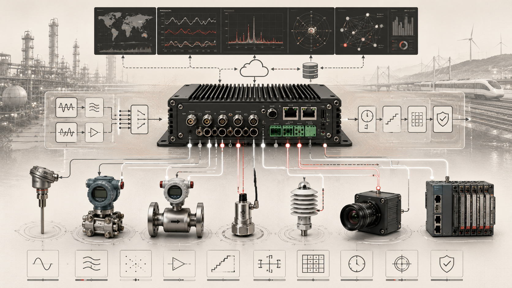
Reference Architecture
A practical embedded data-acquisition architecture can be understood as a measurement chain with explicit evidence boundaries. The exact implementation may use internal ADC peripherals, external SAR or sigma-delta converters, current loops, bridge sensors, digital MEMS sensors, RTD/thermistor front ends, isolated interfaces, DMA, ring buffers, RTOS tasks, Zephyr drivers, vendor HALs, FPGA capture logic, or gateway-side aggregation, but the responsibilities remain consistent.
| Layer | Engineering Role | Acquisition Concern | Evidence Artifact |
|---|---|---|---|
| Physical phenomenon | Defines the quantity to be measured: temperature, pressure, vibration, voltage, current, light, flow, position, humidity, gas concentration, or other state | Range, dynamics, environmental exposure, units, required accuracy | Measurement requirement, sensor selection rationale, operating envelope |
| Transducer layer | Converts the physical phenomenon into an electrical signal or internally converted digital value | Sensitivity, drift, nonlinearity, hysteresis, excitation, placement | Sensor manifest, calibration record, installation note |
| Analog front end | Amplifies, filters, protects, buffers, level-shifts, isolates, or impedance-matches analog signals before conversion | Noise, settling, bandwidth, input protection, anti-aliasing, common-mode range | AFE configuration, filter profile, gain setting, protection design |
| Reference and excitation | Provides ADC reference, sensor excitation, bridge bias, or stable measurement supply | Reference drift, ratiometric behavior, supply noise, thermal effects | Reference specification, excitation profile, drift budget |
| Conversion layer | Samples analog signals through internal or external ADCs | Resolution, ENOB, sample time, conversion latency, aperture jitter, channel count | ADC configuration, sample-rate plan, conversion report |
| Digital sensor bus layer | Reads internally converted sensor data over I2C, SPI, UART, 1-Wire, CAN, or other digital paths | Bus speed, register configuration, CRC/status bits, contention, stale reads | Bus manifest, register map, driver configuration, transaction log |
| Timing and trigger layer | Coordinates sampling intervals, data-ready interrupts, timer triggers, synchronized bursts, and acquisition windows | Timestamp quality, jitter, sampling coherence, ISR latency | Timing profile, trigger policy, synchronization log |
| Buffering and transport layer | Moves samples through DMA, FIFOs, ring buffers, queues, RTOS tasks, or gateway transport | Backpressure, drops, stale data, buffer overrun, memory ownership | Buffer occupancy record, drop counters, DMA status, queue metrics |
| Validation and quality layer | Checks range, saturation, plausibility, calibration state, freshness, signal health, and acquisition fault indicators | Invalid readings, sensor faults, outliers, stuck-at values, drift, missing samples | Quality flags, health status, validation log, diagnostic report |
| Provenance and lineage layer | Preserves source identity, acquisition time, scaling, units, calibration version, transform history, and confidence | Traceability, reproducibility, auditability, downstream interpretability | Measurement schema, metadata record, lineage manifest |
| Application and edge analytics layer | Uses acquired data for control, monitoring, inference, alarms, dashboards, storage, or transmission | Fitness for use, latency, decision authority, evidence retention | Decision log, telemetry record, analytics summary, incident trace |
This architecture makes the measurement path visible. It separates the physical signal from the transducer output, the transducer output from the conditioned signal, the conditioned signal from the digital sample, the digital sample from the validated measurement, and the validated measurement from the application decision. Without those distinctions, embedded systems can confuse electrical readings with physical truth.
Implementation Pattern
A rigorous embedded acquisition implementation begins by defining the measurement purpose before selecting parts or writing drivers. The required accuracy, sampling rate, latency, environmental envelope, calibration approach, and downstream use should determine the sensor, analog front end, converter, bus, timing model, and software architecture.
| Artifact | Purpose | Typical Format |
|---|---|---|
| Measurement requirement | Defines physical quantity, units, range, acceptable error, bandwidth, timing, and decision dependency | Markdown, YAML, engineering requirement table |
| Sensor capability profile | Documents sensor type, range, sensitivity, accuracy, drift, response time, interface, and environmental constraints | YAML, JSON, datasheet-derived manifest |
| Analog front-end profile | Defines gain, filtering, buffering, source impedance assumptions, protection, and anti-aliasing behavior | YAML, schematic notes, design review record |
| ADC configuration | Defines resolution, reference, sample time, channel sequence, oversampling, conversion mode, and trigger source | YAML, HAL configuration, register map |
| Digital bus configuration | Defines bus type, speed, addressing, chip-select behavior, register settings, retry policy, and validation flags | YAML, driver config, device tree, register map |
| Timing and synchronization plan | Defines sampling cadence, jitter tolerance, timestamp source, trigger path, interrupt behavior, and synchronization assumptions | Runbook, timing diagram, test report |
| Buffering policy | Defines FIFO depth, DMA ownership, ring-buffer behavior, drop policy, freshness guarantees, and backpressure response | YAML, firmware comments, runtime metrics |
| Quality-check schema | Defines range checks, saturation checks, stale-data checks, stuck-sensor checks, plausibility rules, and calibration requirements | SQL, JSON Schema, Python/R validation workflow |
| Measurement event schema | Defines sample value, units, channel, acquisition time, processing time, calibration version, quality flags, and lineage fields | SQL, CSV, Parquet schema, JSON Schema |
| Operational monitoring plan | Defines fleet metrics for sensor health, drop rate, timestamp jitter, calibration age, fault frequency, and data completeness | R report, dashboard config, monitoring runbook |
The implementation goal is to make the acquisition chain inspectable. Engineers should be able to reconstruct how a measurement was produced, which hardware and firmware configuration shaped it, whether it met timing and quality requirements, and whether it was safe to use for the downstream decision it influenced.
Research-Grade Framing: Data Acquisition as Measurement Infrastructure
Embedded data acquisition should be framed as measurement infrastructure. It is the layer that determines what the system can know about the physical world. When measurement infrastructure is weak, every higher layer inherits uncertainty: control loops respond to flawed state estimates, predictive models learn from distorted inputs, dashboards present false confidence, and maintenance decisions rest on questionable evidence.
This framing matters because embedded acquisition is often treated as a peripheral concern. A sensor is selected, a driver is written, and values appear in logs. But a real measurement system includes physical placement, mechanical coupling, electrical design, reference stability, analog bandwidth, conversion timing, digital transport, timestamp quality, calibration, validation, and lineage. Each layer can preserve or degrade the relationship between the phenomenon and the record.
| Evidence Dimension | Question | Required Acquisition Evidence |
|---|---|---|
| Physical meaning | What physical quantity does this value represent? | Units, channel identity, sensor type, placement, measurement requirement |
| Signal path | How did the signal move from transducer to digital record? | AFE settings, ADC configuration, bus configuration, transform history |
| Timing | When was the physical state sampled? | Acquisition timestamp, timestamp source, jitter estimate, trigger path |
| Quality | Is the value fit for the intended use? | Range flags, saturation flags, stale-data flags, noise estimate, drop status |
| Calibration | Which scaling and correction assumptions apply? | Calibration version, calibration date, coefficient set, drift interval |
| Freshness | Was the value current when it was used? | Acquisition time, processing time, queue delay, buffer age |
| Lineage | Can the system reconstruct how the value was produced? | Sensor ID, firmware version, driver version, transform stage, metadata record |
A strong embedded acquisition system does not merely produce data. It produces evidence. That evidence is what allows engineers to distinguish real physical change from measurement artifact, sensor drift, electrical noise, bus failure, timestamp error, firmware overload, or downstream processing distortion.
Formal Model: Physical Signal, Measurement Chain, and Digital Record
A useful formal model separates the physical phenomenon, the transducer response, the analog or digital interface, the sampled value, the quality checks, and the application-level measurement record. Let \(s(t)\) represent the physical signal of interest, \(g(\cdot)\) the transducer response, \(h(\cdot)\) the analog front-end or sensor-internal conditioning path, \(q(\cdot)\) the quantization and conversion process, and \(m_k\) the digital measurement record at sample index \(k\).
v(t) = g(s(t)) + n_s(t)
\]
Interpretation: The transducer converts the physical signal \(s(t)\) into an electrical or internal sensor-domain signal \(v(t)\), while sensor noise, drift, placement effects, and nonlinearity contribute \(n_s(t)\).
u(t) = h(v(t)) + n_a(t)
\]
Interpretation: The signal-conditioning path \(h(\cdot)\) amplifies, filters, buffers, protects, or otherwise shapes the transducer signal. Analog noise, reference effects, grounding problems, and settling error appear in \(n_a(t)\).
x_k = q(u(t_k))
\]
Interpretation: The converter samples the conditioned signal at acquisition time \(t_k\) and maps it into a digital value \(x_k\). The quality of \(x_k\) depends on sample timing, quantization, reference stability, aperture behavior, and front-end settling.
m_k = \{x_k, t_k, c, r, \gamma, Q_k\}
\]
Interpretation: A trustworthy measurement record \(m_k\) includes not only the value \(x_k\), but acquisition time \(t_k\), channel identity \(c\), reference or scaling state \(r\), calibration version \(\gamma\), and quality flags \(Q_k\).
This formal structure matters because an embedded measurement is not only a scalar value. It is a value embedded in a chain of physical, electrical, temporal, and software assumptions. A system that preserves those assumptions can diagnose failures, reproduce analyses, and judge whether a measurement is fit for use.
What Are Data Acquisition and Embedded Sensor Interfaces?
Data acquisition is the process by which an embedded system samples physical signals and converts them into digital information that software can store, analyze, transmit, or act upon. Embedded sensor interfaces are the electrical, timing, and logical structures that make this possible: analog inputs, ADCs, sensor buses, timing sources, data-ready interrupts, DMA paths, ring buffers, driver APIs, validation logic, and higher-level sensing frameworks.
In embedded contexts, acquisition usually falls into two broad classes. The first is analog acquisition, where the system measures a voltage, current, resistance-derived voltage, bridge signal, or other analog quantity through an ADC after necessary conditioning. The second is digital sensor interfacing, where a sensor contains its own conversion and exposes formatted data over a digital bus such as I2C or SPI. Many practical systems combine both patterns, using analog acquisition for some channels and digital sensors for others.
The architectural importance of acquisition lies in where error enters. Measurement error can arise at the sensor element, in signal conditioning, during conversion, across transport buses, through clock and timestamp behavior, in buffering, or in software validation. A robust acquisition design therefore defines not only how signals are read, but where uncertainty is introduced, how it is bounded, and how the system decides whether the resulting data are fit for use.
A minimal acquisition path can produce values. A mature acquisition architecture produces measurements: values with units, timing, quality, lineage, calibration, and context.
Transduction and Measurement Chain Fundamentals
Every data-acquisition system begins with transduction: the conversion of a physical phenomenon into an electrical signal or internally represented sensor state. A temperature probe may vary resistance, a pressure sensor may produce a small differential voltage, a photodiode may generate current, a current transformer may produce a proportional signal, and an accelerometer may expose values through either analog or digital interfaces. From the system’s perspective, these are not yet usable measurements. They are raw signal conditions that must travel through a measurement chain before becoming stable data.
This chain usually includes the sensor element, mechanical or environmental coupling, excitation or bias circuitry where needed, analog conditioning, conversion or digital readout, software acquisition logic, timestamping, validation, and often some form of local filtering or compensation. The chain matters because errors accumulate across it. A well-specified ADC cannot rescue a poorly biased sensor, and a clean digital interface cannot compensate for a badly chosen physical sensing element.
Good embedded architecture treats the acquisition chain as one system rather than as independent parts purchased from different domains. The sensor, board layout, reference source, power supply, grounding strategy, firmware driver, sampling schedule, and data schema are all part of the same measurement argument.
That systems view is especially important because acquisition often drives control or inference directly. A value is not merely logged; it may trigger alarms, update actuators, estimate system state, feed an edge model, or change infrastructure behavior. If the measurement chain is weak, the device’s higher-order intelligence is weak as well.
Analog Front Ends, Signal Conditioning, and Anti-Aliasing
Many embedded sensors produce analog outputs that are too small, too noisy, too offset, too high impedance, too exposed, or too broadband to be passed directly into an ADC. This is why analog front ends matter. Signal conditioning may include amplification, buffering, impedance matching, level shifting, filtering, isolation, surge protection, electrostatic discharge protection, common-mode rejection, and sensor excitation.
The analog front end should be designed around both the signal and the converter. The ADC input may require a low-impedance source during acquisition. A multiplexer may introduce charge injection or channel memory. A programmable gain amplifier may require settling time. A protection network may add capacitance or leakage. A filter that looks clean in isolation may interact with the sampling capacitor or with multiplexed channel sequencing.
Anti-aliasing is one of the most important conditioning functions. Once a signal is sampled, frequency content above the effective sampling limit can fold back into the measured band as aliasing. In multiplexed systems, filtering must also be balanced against settling time. A filter that improves noise performance may still produce invalid measurements if its time constant prevents the input from settling before the conversion window closes.
Field wiring and analog noise also shape the front end. Grounding, shielding, cable routing, common-mode interference, source impedance, leakage, and environmental exposure can materially distort the measured signal before it reaches the converter. In embedded devices deployed in industrial, automotive, agricultural, infrastructure, or outdoor environments, front-end design is inseparable from board layout, enclosure design, connector choice, and physical installation.
ADC Architecture, Resolution, and Sampling Behavior
The analog-to-digital converter is the active interface between the analog and digital portions of an embedded system. ADC choice is architectural. It determines not only how many bits a signal receives, but how quickly it can be sampled, how much power it consumes, how many channels it can support, what input behavior it requires, how conversion latency appears, and what kinds of front-end design it rewards or punishes.
Different ADC architectures suit different acquisition problems. Successive-approximation-register converters are often favored for multiplexed embedded measurement because of relatively direct conversion behavior, moderate-to-high speed, and flexible channel handling. Sigma-delta converters can offer high resolution and strong noise performance for lower-bandwidth signals, but their digital filtering and latency behavior must be understood. Pipeline and high-speed converters serve different acquisition contexts where throughput dominates, while many MCU-integrated ADCs trade precision, cost, convenience, and power in ways that must be verified experimentally rather than accepted from headline bit depth.
Resolution alone is not enough. An ADC with many nominal bits can still produce poor practical data if reference stability, analog settling, acquisition time, aperture jitter, source impedance, layout noise, or front-end noise are weak. Engineers often care more about effective number of bits, total error, noise-free resolution, integral and differential nonlinearity, conversion latency, and repeatability than about nominal resolution alone.
Converter selection should always be made in the context of the entire measurement path. The right question is not “How many bits does the ADC have?” It is “How much trustworthy information does this acquisition chain preserve under the operating conditions that matter?”
Multiplexing, Settling, and Channel Interaction
Embedded devices often need to measure multiple channels with one ADC, which makes multiplexing attractive. But multiplexing introduces its own timing discipline. When the converter switches from one channel to another, the input path, multiplexer, sampling capacitor, programmable gain stage, source impedance, filter network, and ADC front end must settle before the conversion is trustworthy.
This matters because channel-to-channel interaction can quietly corrupt data. A full-scale signal on one channel can influence the next if the front end has not settled. High source impedance can increase acquisition error. A channel with a large step change can leave memory in the sampling network. Switching speed that looks acceptable in a digital timing diagram may still be physically wrong for the analog path.
In many embedded systems, apparent “sensor noise” is actually acquisition-path settling error, charge injection, insufficient sample time, source impedance mismatch, or dc crosstalk between adjacent channels. These errors may be intermittent and difficult to diagnose because they depend on channel order, signal level, sampling rate, temperature, and firmware timing.
Good multiplexed acquisition therefore requires explicit timing margins, awareness of source impedance, careful channel ordering, dummy conversions where necessary, buffer stages for difficult channels, and validation tests that look for adjacent-channel contamination. Multiplexing is efficient, but it is not free.
Digital Sensor Interfaces: I2C, SPI, and Beyond
Many modern sensors include internal conversion and expose data digitally rather than as raw analog signals. In embedded systems, I2C and SPI are among the most common interfaces for such devices, though UART, CAN, 1-Wire, SDI-12, MIPI interfaces, industrial fieldbuses, and other protocols appear in specific environments.
The choice between I2C and SPI is architectural rather than merely conventional. I2C can simplify wiring and multi-device bus sharing, but it introduces address management, pull-up dependence, shared-bus behavior, clock stretching, bus recovery concerns, and throughput limits. SPI often provides higher speed and simpler framing at the link layer, but usually at the cost of more wires, per-device chip-select logic, and greater need for clean board-level signal integrity at higher speeds.
Digital interfaces solve some problems and create others. They avoid certain analog-noise burdens and offload conversion into the sensor, but they also make the system dependent on bus integrity, device register semantics, configuration correctness, driver discipline, transaction validation, and status handling. A digital sensor is not necessarily a simpler measurement system; it is a differently partitioned one.
A mature digital sensor interface should verify configuration after boot, detect stale readings where possible, handle sensor reset states, check status and error bits, validate CRC or parity when available, manage bus timeouts, and distinguish acquisition time from readout time. Without these practices, digital sensors can produce clean-looking values that conceal configuration drift, bus retries, or stale internal conversion results.
Timing, Triggering, and Sampling Coordination
Acquisition quality depends on when measurements are taken, not only on how. Some systems require fixed periodic sampling, others event-triggered reads, and others burst capture during anomalies, control-state changes, or environmental transitions. The timing model should reflect the dynamics of the physical phenomenon and the decision that depends on it.
Timing discipline is especially important when multiple sensors must be interpreted together. An IMU, pressure sensor, temperature channel, and current measurement sampled at different moments may not form a coherent state estimate unless timestamping and synchronization are handled carefully. The same is true in distributed acquisition systems where gateway-side fusion depends on knowing acquisition timing with enough fidelity to interpret relationships among channels.
Triggering also shapes power, bus behavior, and latency. A data-ready interrupt can preserve efficiency and reduce unnecessary polling, while periodic forced reads may simplify scheduling but increase energy use and bus traffic. Timer-triggered ADC conversion can improve regularity, while software-triggered acquisition may be easier to implement but more exposed to jitter. DMA can improve throughput but requires careful buffer ownership and completion semantics.
Good embedded acquisition design chooses timing models that reflect both the signal dynamics and the operational constraints of the device. Timestamp quality should be treated as part of measurement quality, not as a logging convenience added later.
Buffering, DMA, and Embedded Data Paths
Once data are acquired, they still must move safely through the embedded system. Buffers, queues, DMA, ISR handoff, task-level processing, local storage, and telemetry transport all influence whether acquisition remains reliable under load.
DMA can reduce CPU overhead and improve throughput when sampling rates rise or channels multiply, but it also complicates memory ownership and timing analysis. Double buffering, circular buffers, cache coherency, interrupt completion flags, and producer-consumer synchronization all require careful design. A DMA transfer that is efficient but poorly synchronized can produce data races, stale windows, or subtle corruption.
Buffering can absorb bursty acquisition, but it can also hide overload until stale or dropped data accumulate. Ring buffers should expose occupancy, drops, overruns, and sample age. Queues should distinguish backpressure from silent loss. Data paths should define what happens when consumers cannot keep pace with producers: drop oldest, drop newest, reduce sampling, aggregate locally, raise an alarm, or enter a degraded mode.
The architectural point is simple: measurement quality is lost just as easily in buffering and software transport as in the analog front end. A strong acquisition chain remains coherent from input pin to usable application data.
Noise, Reference Stability, and Measurement Integrity
Measurement integrity depends on more than nominal converter resolution. Noise, reference drift, grounding, source impedance, sampling-capacitor charging, board layout, digital switching noise, thermal gradients, cable length, connector quality, and physical installation all influence the practical quality of acquired data.
Reference stability is especially important. An ADC measures relative to its reference, so unstable or noisy references degrade every reported value. In some systems, ratiometric measurement can reduce sensitivity to supply variation. In others, an external precision reference, careful decoupling, isolation, or temperature compensation may be required. The reference path should be treated as part of the measurement chain, not as a background supply detail.
Similarly, a beautifully conditioned sensor path can still yield low-integrity data if timing jitter, bus retries, stale register values, dropped buffers, or poor software validation corrupt the acquisition record downstream. Measurement integrity is cumulative and fragile.
Strong embedded acquisition systems make uncertainty visible. They preserve calibration assumptions, detect out-of-range conditions, expose acquisition faults where possible, distinguish raw measurements from filtered or inferred values, and record enough metadata to support diagnosis. Numbers alone are not evidence unless the system can explain how they were produced.
Firmware Architecture for Sensor Acquisition
Firmware decides whether acquisition features are used well. It configures ADC sequences, manages sensor buses, applies timing margins, handles data-ready events, moves samples into buffers, validates values, and exposes measurements to higher layers. Hardware can provide capability, but firmware determines whether that capability becomes reliable measurement.
Good firmware architecture keeps the signal path intelligible. It should make clear which channels are sampled when, which conversions are blocking or asynchronous, which reads are safe in interrupt context, how calibration is applied, where units are converted, how errors are represented, and what happens when acquisition fails or returns stale data. Poor firmware often hides acquisition assumptions in scattered drivers, incidental delays, and unexplained constants.
A robust firmware design usually separates low-level device access from measurement semantics. The driver may know how to read a register or trigger an ADC conversion, but the measurement layer should know units, scaling, calibration, timestamps, quality flags, and application relevance. This separation helps prevent a raw register value from being mistaken for a validated physical measurement.
Because acquisition often feeds control or analytics, firmware should also preserve provenance. Systems become more trustworthy when they can distinguish raw samples, conditioned values, compensated measurements, fused estimates, and communications-ready payloads as separate stages rather than collapsing them into one undocumented number stream.
Timestamping, Provenance, and Measurement Lineage
A measurement is not only a value. It is also a record of when, how, and under what assumptions that value was produced. Embedded acquisition systems become much more trustworthy when they preserve timestamp quality, channel identity, units, scaling assumptions, calibration version, firmware version, driver configuration, and any transformation applied between raw capture and final output.
This matters because many acquisition errors do not show up as obviously impossible values. They show up as values with weak lineage: samples whose timing is uncertain, readings whose calibration state is unclear, or fused outputs that no longer reveal which inputs were direct measurements and which were derived. Without provenance, debugging becomes guesswork and downstream analysis becomes more fragile.
Timestamping deserves special attention. A timestamp should represent the acquisition event as closely as possible, not merely the time when software happened to process or transmit the data. For some systems, the distinction is minor. For control, vibration analysis, sensor fusion, distributed monitoring, and event reconstruction, the distinction can be decisive.
Strong measurement systems preserve lineage across the full acquisition path. They make it possible to answer basic questions later: which sensor produced this value, when exactly was it sampled, what reference or calibration was active, what filtering was applied, whether the value was raw, compensated, averaged, or inferred, and whether quality checks passed.
Runtime Validation and Measurement Health Checks
Runtime validation turns acquisition from a passive readout process into an actively monitored measurement system. The goal is not to prove that every value is perfect. The goal is to detect when the system no longer has enough confidence in the acquisition chain to use the data normally.
Common validation checks include range limits, saturation detection, stale-data detection, timestamp jitter, missing samples, bus timeout counters, CRC failures, sensor self-test status, ADC overrun flags, buffer occupancy, drop counts, reference monitoring, calibration age, and plausibility checks across related channels. For example, a temperature sensor that never changes may be healthy in a stable room but suspicious in a system where nearby power electronics are heating rapidly. A pressure reading may be within range but physically inconsistent with a related flow measurement.
Validation should be attached to the measurement record. A downstream application should not need to infer quality from the value alone. Quality flags, status fields, and confidence indicators allow control logic, telemetry systems, and analytics workflows to handle uncertain measurements differently from trusted ones.
Runtime validation also supports field operations. When an acquisition problem appears in deployed equipment, engineers need to know whether the failure is likely a sensor failure, wiring problem, front-end issue, reference issue, bus problem, timestamp problem, firmware overload, or environmental condition. Measurement health checks make that diagnosis possible without requiring every incident to begin from raw guesswork.
From Samples to Data Products
Embedded acquisition does not end at sample capture. The sample becomes a data product only after it is validated, contextualized, transformed, and made usable for control, analytics, storage, or communication. A raw ADC code, for example, may become a voltage, then a calibrated pressure, then a filtered pressure trend, then an alarm state, then a telemetry record. Each transformation adds meaning, but each transformation can also obscure the original measurement if lineage is not preserved.
This is especially important in edge systems. Local devices may compress, aggregate, downsample, classify, or selectively transmit acquisition records to conserve bandwidth and power. These transformations can be valuable, but they must not destroy the evidence needed to understand what happened in the field. A dashboard that shows only the final derived value may be insufficient when engineers need to diagnose aliasing, sensor drift, missing samples, or calibration failure.
A mature acquisition architecture therefore treats samples, measurements, features, events, and telemetry as distinct data products. Each should carry the metadata needed for its use: units, timestamp, channel, quality flag, transform version, calibration version, and source device. That discipline supports reproducibility, auditability, and long-term trust in sensor-driven systems.
Mathematical Lens: Sampling, Quantization, Settling, Error, and Timestamp Quality
A mathematical view of embedded acquisition helps engineers connect physical signal behavior with digital measurement limits. Let \(f_s\) be the sampling frequency, \(f_{\max}\) the highest frequency component that must be preserved, \(N\) the converter resolution in bits, \(V_{\mathrm{ref}}\) the ADC reference, \(T_s\) the sampling period, \(T_{\mathrm{acquire}}\) the acquisition window, \(T_{\mathrm{convert}}\) the conversion time, \(T_{\mathrm{settle}}\) the required settling time, \(R_s\) the effective source resistance, \(C_{\mathrm{in}}\) the ADC input capacitance, and \(e_k\) the total measurement error at sample \(k\).
f_s \geq 2f_{\max}
\]
Interpretation: Sampling must be fast enough to preserve the signal content of interest. Practical designs usually require margin above the ideal Nyquist condition because anti-aliasing filters, transition bands, timing jitter, and reconstruction needs all consume engineering headroom.
\Delta = \frac{V_{\mathrm{ref}}}{2^N}
\]
Interpretation: The ideal ADC code width \(\Delta\) depends on reference voltage and nominal resolution. Practical resolution is reduced by noise, reference instability, nonlinearity, layout coupling, source impedance, and front-end behavior.
\mathrm{ENOB} = \frac{\mathrm{SNR}_{\mathrm{dB}} – 1.76}{6.02}
\]
Interpretation: Effective number of bits connects converter noise performance to usable resolution. A nominal 12-bit converter does not necessarily deliver 12 bits of trustworthy information in a real embedded measurement chain.
T_s \geq T_{\mathrm{acquire}} + T_{\mathrm{convert}} + T_{\mathrm{settle}}
\]
Interpretation: The sampling period must allow acquisition, conversion, and analog settling. Multiplexed systems often fail when channel switching is scheduled faster than the analog path can settle.
e_{\mathrm{settle}} \approx \Delta V e^{-T_{\mathrm{acquire}}/(R_s C_{\mathrm{in}})}
\]
Interpretation: Settling error decays with acquisition time and the source-resistance/input-capacitance time constant. High source impedance, fast channel switching, or insufficient acquisition windows can leave residual error from the previous channel.
e_k = e_{\mathrm{sensor}} + e_{\mathrm{afe}} + e_{\mathrm{ref}} + e_{\mathrm{quant}} + e_{\mathrm{timing}} + e_{\mathrm{cal}} + e_{\mathrm{transport}}
\]
Interpretation: Total measurement error is distributed across the sensor, analog front end, reference source, quantization, timing behavior, calibration, and software transport. Debugging acquisition requires locating which term dominates under real operating conditions.
J_k = |t_{k}^{\mathrm{actual}} – t_{k}^{\mathrm{scheduled}}|
\]
Interpretation: Timestamp jitter \(J_k\) measures the difference between actual acquisition time and scheduled acquisition time. For sensor fusion, vibration analysis, event reconstruction, and control, timestamp error can be as important as value error.
These formulas are intentionally compact. Their purpose is not to reduce acquisition design to a few equations, but to make hidden constraints explicit. Sampling rate, usable resolution, acquisition time, settling behavior, total error, timestamp quality, and transport reliability must be engineered together.
Python Workflow: Sensor Acquisition Integrity and Sampling-Chain Simulation
The companion Python workflow models a representative embedded acquisition chain. It loads sample acquisition events and channel manifests, simulates physical signal behavior, ADC quantization, timestamp jitter, buffer age, stale readings, bus retries, and quality flags, then writes outputs for engineering review. It is intentionally structured as a predeployment validation scaffold rather than a decorative data example.
The workflow is designed to answer practical questions. Does the selected sampling rate preserve the signal of interest? Does quantization meaningfully limit resolution? Do timestamp deviations exceed the tolerance needed for downstream analysis? Do buffer delays create stale measurements? Do bus retries or stale reads indicate interface-level weakness? Which measurements should be marked as unfit for use before they reach control logic, dashboards, or edge analytics?
The Python workflow should produce at least four outputs: a cleaned measurement-event table, an acquisition-quality summary, plots of raw versus acquired signals, and a validation report showing failed checks by device, channel, and condition. In a production system, this workflow could be adapted into a hardware-in-the-loop test harness or a predeployment validation notebook.
The goal is not to replace bench testing. It is to make the engineering assumptions explicit before and after hardware testing. Simulation helps identify which parameters require measurement, which risks deserve instrumentation, and which quality checks should be added to firmware and telemetry schemas.
R Workflow: Fleet-Level Sensor Quality and Measurement Reliability Reporting
The companion R workflow treats acquisition as a fleet-level reliability and measurement-quality problem. It summarizes warning rates, timestamp jitter, buffer age, stale readings, bus retries, and acquisition health across devices and sites, then writes CSV and visual outputs suitable for engineering review.
This matters because sensor problems often appear only after deployment. One device may have clean data on the bench but degrade when installed near electrical noise. Another may show timestamp drift after long uptime. Another may produce sporadic I2C errors during high bus traffic. Another may remain within physical range while reporting stale internal sensor values. Fleet-level reporting helps distinguish isolated faults from systematic acquisition design weaknesses.
The R workflow should generate CSV summaries and visual reports suitable for engineering review. Useful outputs include device health rankings, channel-level quality dashboards, calibration-age summaries, jitter distributions, sample completeness by site, and acquisition-fault frequency over time. These outputs can support maintenance planning, firmware fixes, validation campaigns, and data-quality gates for downstream analytics.
The point is to treat sensor acquisition as an observable runtime system. If acquisition quality cannot be monitored, it cannot be governed.
Systems Code: ADC Drivers, Sensor Buses, DMA, Firmware, Rust Validation, Go Telemetry, PYNQ, HDL, and Bash
The companion systems stack demonstrates how acquisition concerns appear across embedded and edge implementation layers.
The C example focuses on firmware-adjacent acquisition logic: raw code handling, timing checks, stale-read detection, quality classification, and diagnostic status. The C++ example models an acquisition state machine that separates configuration, sampling, validation, degraded operation, and publishing. The Rust example validates sensor-interface manifests and checks that required fields are present before a configuration is accepted. The Go example sketches a lightweight event router that reads acquisition events and summarizes warning counts and timestamp behavior across a fleet.
MicroPython provides a prototype for sensor polling, local validation, and MQTT-style telemetry payload preparation on constrained boards. TinyML appears only where acquisition feeds local classification, anomaly detection, or feature extraction. PYNQ support demonstrates hardware-assisted sampling, buffering, or signal preprocessing. HDL examples include timestamp counters, stream-valid framing, trigger logic, FIFO-style buffering, and simple acquisition-state control.
The Bash scripts tie these pieces together. They validate manifests, run Python and R workflows, generate outputs, and check that the expected repository structure exists. The goal is not to make every article a full production implementation. The goal is to provide a coherent engineering scaffold that mirrors the real acquisition problems discussed in the article.
Technical Verification Gates
A technical-rigor review should force the acquisition design through explicit verification gates before publication, deployment, or reuse as a reference design. These gates prevent a measurement chain from being validated only by the fact that plausible numbers appear in a log.
| Gate | Engineering Question | Evidence to Preserve |
|---|---|---|
| Measurement requirement gate | Is the measurand, range, bandwidth, accuracy need, latency need, and downstream decision clearly defined? | Requirement table, physical units, uncertainty target, operating envelope |
| Analog path gate | Do the sensor, excitation, reference, filtering, source impedance, protection, and ADC input behavior form a coherent signal path? | AFE configuration, settling calculation, anti-aliasing assumptions, reference budget |
| Conversion gate | Does the ADC configuration deliver usable resolution and timing under real operating conditions? | ENOB estimate, sample-time configuration, conversion timing, oversampling settings, bench trace |
| Digital interface gate | Are bus transactions validated rather than assumed? | I2C/SPI register configuration, status checks, timeout policy, retry counters, CRC/error flags where available |
| Timestamp gate | Does the timestamp represent acquisition time rather than delayed processing or upload time? | Timestamp source, trigger path, jitter measurement, queue-delay evidence |
| Buffering gate | Can the system detect overload, dropped samples, stale values, and backpressure? | DMA state, ring-buffer occupancy, drop counters, sample age, queue policy |
| Calibration gate | Can each value be traced to a calibration state and scaling assumption? | Calibration version, coefficient record, calibration age, reference standard, firmware compatibility |
| Operational evidence gate | Can field engineers distinguish physical change from acquisition-system failure? | Quality flags, health counters, validation logs, telemetry schema, fleet-level reports |
These gates are deliberately evidence-oriented. A technically rigorous acquisition system is not validated by a successful demo alone. It is validated by preserved evidence that the measurement path remains coherent from physical signal to digital record under the operating conditions that matter.
Testing and Validation
Testing embedded acquisition requires software tests, bench validation, and physical or hardware-in-the-loop validation. Unit tests can verify scaling, range checks, timestamp parsing, buffer behavior, register decoding, and manifest structure. Integration tests can simulate bus failures, missing samples, out-of-range readings, stale data, and malformed telemetry. Hardware-in-the-loop tests can validate timing, settling, reference behavior, channel interaction, DMA behavior, and real sensor dynamics.
A good validation strategy includes at least five levels. First, configuration validation confirms that channel maps, units, sampling rates, calibration versions, and bus settings are coherent. Second, firmware tests confirm that drivers handle errors, timeouts, and degraded states correctly. Third, acquisition tests confirm that sampled values reflect known inputs within error budgets. Fourth, telemetry tests confirm that measurement records preserve lineage and quality. Fifth, operational tests confirm that fleet monitoring can detect drift, missing data, and sensor faults.
Validation should also test negative cases. Systems should be deliberately exposed to out-of-range inputs, disconnected sensors, noisy supplies, bus stalls, incorrect calibration, timestamp delay, buffer pressure, and channel switching stress. A measurement system that only works under ideal conditions is not an engineering-grade acquisition system.
Operational Signals and Acquisition Observability
Acquisition observability is the ability to see whether the measurement chain is functioning as intended after deployment. It requires telemetry beyond the measured value itself.
Useful operational signals include sample counts, missing-sample counts, buffer drops, conversion overruns, bus retry counts, bus timeout counts, CRC failures, data-ready interrupt frequency, timestamp jitter, queue age, calibration age, stale-register indicators, reference-voltage status, sensor self-test status, and quality-flag distributions. These signals help engineers distinguish real environmental behavior from acquisition-system failure.
Observability should be proportional to the system’s importance. A hobby sensor logger may not need extensive evidence. An industrial monitor, safety-adjacent device, environmental compliance system, infrastructure sensor, or medical-adjacent embedded device needs stronger visibility into measurement health. The more consequential the downstream decision, the more disciplined the acquisition evidence should be.
The best acquisition systems are not only accurate at deployment. They are diagnosable over time.
Common Failure Modes
Embedded acquisition failures often appear as ordinary-looking numbers. That is what makes them dangerous. A system may continue to emit values even when the measurement chain has become unreliable.
Common analog failure modes include reference drift, insufficient settling, aliasing, input saturation, source impedance mismatch, ground loops, crosstalk, leakage, poor shielding, sensor aging, and calibration drift. Common digital-sensor failure modes include stale internal conversion values, register misconfiguration, bus contention, clock stretching problems, missing status checks, timeout mishandling, and incorrect scaling. Common firmware failure modes include blocking reads in timing-sensitive contexts, buffer overrun, dropped samples without counters, incorrect timestamping, race conditions, and loss of provenance.
A particularly important failure mode is false precision. A system may report many decimal places even when the acquisition chain cannot support that level of accuracy. Precision in representation should not be confused with precision in measurement.
Another important failure mode is silent degradation. The acquisition system may continue producing values after a sensor fault, reference problem, or timing issue. Strong designs therefore include quality flags, diagnostic counters, degraded modes, and operational alerts.
Trade-Offs in Embedded Data Acquisition Design
Data acquisition in embedded devices is shaped by trade-offs that cannot all be optimized at once. Higher resolution may increase power, cost, conversion time, and sensitivity to layout and reference quality. More aggressive filtering may improve noise performance while adding latency and settling constraints. Faster buses may simplify throughput while increasing complexity, energy use, or signal-integrity risk. Multiplexing saves hardware cost but adds settling and channel-interaction concerns. Local digital sensors reduce analog burden but increase dependence on bus and driver correctness.
The right design depends on the measurement’s purpose. Control loops, environmental monitoring, wearable sensing, vibration analysis, industrial instrumentation, robotics, precision agriculture, power systems, and edge AI all impose different requirements on timing, noise, power, bandwidth, and interpretability.
Good acquisition architecture is proportional. It matches the measurement chain to the physical signal and to the system decision that will depend on that signal. It avoids both underengineering and ornamental overengineering. The aim is not maximum specification in every dimension. The aim is trustworthy measurement for the job at hand.
Applications in Embedded and Edge Systems
Data acquisition and sensor interfacing appear across industrial monitoring, environmental sensing, robotics, medical devices, wearables, precision agriculture, power systems, transportation, buildings, laboratories, distributed infrastructure, and edge instrumentation. In each case, the system’s usefulness depends on whether measurements remain physically meaningful after conversion, transport, and software handling.
In industrial monitoring, acquisition quality determines whether vibration, current, temperature, and pressure signals can support maintenance decisions. In environmental monitoring, calibration, timestamping, and data completeness shape whether measurements can support scientific or public-interest claims. In robotics, timing and sensor fusion determine whether perception and control remain coherent. In power systems, sampling and synchronization determine whether events can be reconstructed accurately. In edge AI, acquisition quality determines whether local models are learning from or acting on meaningful signals.
That is why acquisition design is foundational to embedded and edge computing more broadly: it defines the quality of the device’s contact with reality.
Engineer Checklist
| Question | Why It Matters |
|---|---|
| Is the physical quantity, range, unit, and required accuracy defined? | Prevents sensor selection and ADC design from drifting away from the real measurement need. |
| Is the analog front end matched to the sensor and converter? | Protects against noise, impedance, bandwidth, settling, and input-range problems. |
| Is the sampling rate justified by the signal bandwidth? | Reduces aliasing and ensures the sampled signal preserves meaningful dynamics. |
| Are timestamp source and acquisition time clearly defined? | Supports sensor fusion, event reconstruction, control, and downstream analysis. |
| Are quality flags attached to measurements? | Allows applications to distinguish trusted, degraded, stale, saturated, or invalid data. |
| Are calibration version and scaling assumptions preserved? | Supports reproducibility, maintenance, and long-term measurement integrity. |
| Are buffer drops, bus errors, and stale reads observable? | Prevents acquisition failures from becoming silent data-quality failures. |
| Can engineers reconstruct the full measurement lineage? | Enables debugging, auditability, and responsible use of sensor-derived data. |
GitHub Repository
This article is supported by a companion workflow that treats embedded data acquisition as a full measurement-chain problem: sensor requirements, analog front-end assumptions, ADC configuration, digital bus behavior, timing, buffering, validation, provenance, fleet reporting, and systems-code scaffolding.
Complete Code RepositoryThe companion repository includes Python, R, SQL, C, C++, Rust, Go, MicroPython, TinyML, PYNQ, HDL, Bash, YAML/JSON configuration, notebooks, tests, docs, data, outputs, and article-specific engineering workflows.
Where This Fits in the Series
This article extends the foundations established in Embedded Systems Architecture, Microcontrollers and System-on-Chip Design, Firmware, Hardware Abstraction, and Device Control, and Environmental Sensor Networks by focusing on how physical signals enter embedded devices as trustworthy digital data.
It also prepares the way for later work on distributed monitoring systems, internet-of-things sensor architectures, calibration, noise, measurement integrity, edge analytics, embedded reliability, and sensor-driven infrastructure systems.
Related articles
- Embedded Systems Architecture
- Microcontrollers and System-on-Chip Design
- Firmware, Hardware Abstraction, and Device Control
- Environmental Sensor Networks
- Low-Power Embedded System Design
- Reliability and Fault Tolerance in Embedded Devices
Further reading
- Microchip (2020) Analog Sensor Measurement and Acquisition. Available at: https://ww1.microchip.com/downloads/aemDocuments/documents/MCU08/ApplicationNotes/ApplicationNotes/Analog-Sensor-Measurement-and-Acquisition-DS00003521A.pdf.
- Microchip (2021) Maximizing the Signal: Tips and Tricks to Properly Acquiring Analog Signals. Available at: https://ww1.microchip.com/downloads/aemDocuments/documents/MCU08/ApplicationNotes/ApplicationNotes/Max-Signal-Properly-TipsTrick-Acq-Analog-Signals-DS00004225.pdf.
- Analog Devices (n.d.) Data Converter Applications, Chapter 8. Available at: https://www.analog.com/media/en/training-seminars/design-handbooks/Data-Conversion-Handbook/Chapter8.pdf.
- Zephyr Project (n.d.) Analog-to-Digital Converter (ADC). Available at: https://docs.zephyrproject.org/latest/hardware/peripherals/adc.html.
- Zephyr Project (n.d.) Inter-Integrated Circuit (I2C) Bus. Available at: https://docs.zephyrproject.org/latest/hardware/peripherals/i2c.html.
- Zephyr Project (n.d.) Serial Peripheral Interface (SPI) Bus. Available at: https://docs.zephyrproject.org/latest/hardware/peripherals/spi.html.
- Texas Instruments (2024) Improving MSPS ADC’s SFDR While Relaxing AAF Requirements and Using Integrated DDC Features. Available at: https://www.ti.com/lit/pdf/sbaa669.
References
- Analog Devices (n.d.) A Simple ADC Comparison Matrix. Available at: https://www.analog.com/en/resources/technical-articles/a-simple-adc-comparison-matrix.html.
- Analog Devices (n.d.) Data Converter Applications, Chapter 8. Available at: https://www.analog.com/media/en/training-seminars/design-handbooks/Data-Conversion-Handbook/Chapter8.pdf.
- Microchip (2020) Analog Sensor Measurement and Acquisition. Available at: https://ww1.microchip.com/downloads/aemDocuments/documents/MCU08/ApplicationNotes/ApplicationNotes/Analog-Sensor-Measurement-and-Acquisition-DS00003521A.pdf.
- Microchip (2021) Maximizing the Signal: Tips and Tricks to Properly Acquiring Analog Signals. Available at: https://ww1.microchip.com/downloads/aemDocuments/documents/MCU08/ApplicationNotes/ApplicationNotes/Max-Signal-Properly-TipsTrick-Acq-Analog-Signals-DS00004225.pdf.
- National Instruments (n.d.) Field Wiring and Noise Considerations for Analog Signals. Available at: https://www.ni.com/en/shop/data-acquisition/measurement-fundamentals/field-wiring-and-noise-considerations-for-analog-signals.html.
- Texas Instruments (2024) Improving MSPS ADC’s SFDR While Relaxing AAF Requirements and Using Integrated DDC Features. Available at: https://www.ti.com/lit/pdf/sbaa669.
- Zephyr Project (n.d.) Analog-to-Digital Converter (ADC). Available at: https://docs.zephyrproject.org/latest/hardware/peripherals/adc.html.
- Zephyr Project (n.d.) Inter-Integrated Circuit (I2C) Bus. Available at: https://docs.zephyrproject.org/latest/hardware/peripherals/i2c.html.
- Zephyr Project (n.d.) Serial Peripheral Interface (SPI) Bus. Available at: https://docs.zephyrproject.org/latest/hardware/peripherals/spi.html.
- Zephyr Project (n.d.) Sensors. Available at: https://docs.zephyrproject.org/latest/hardware/peripherals/sensor/index.html.