
Last Updated May 14, 2026
Embedded monitoring devices for field observation are edge-based infrastructures of environmental observability through which local environmental signals are converted into persistent, time-structured, and operationally usable records under the constraints of real-world field conditions. They integrate sensing elements, embedded control, timing, power systems, local storage, protective enclosures, firmware logic, communications, diagnostics, and maintenance workflows in order to measure environmental change where direct human presence is sparse, intermittent, expensive, unsafe, or too slow for the phenomena of interest. In this sense, an embedded monitoring device is not merely a sensor package, data logger, or miniature instrument. It is a field-resident measurement system that makes environmental processes legible by persisting at the edge of observation long enough to capture what episodic fieldwork would otherwise miss.
Field observation creates a distinctive technical and epistemic problem because environmental conditions are variable, remote, power-constrained, and hostile to instrumentation. Moisture ingress, thermal stress, biofouling, sediment load, corrosion, vibration, wildlife disturbance, communications dropout, battery depletion, enclosure failure, clock drift, firmware instability, and delayed maintenance all shape whether a device remains trustworthy outside controlled settings. Embedded monitoring devices therefore sit at the intersection of environmental sensing, embedded systems engineering, field operations, and observational inference. Their significance lies not only in what they measure, but in whether they can remain powered, synchronized, calibrated, protected, and interpretable long enough for their data to support real environmental judgment.
The deeper importance of embedded field devices is that they transform monitoring into a problem of autonomous presence. A field crew can sample episodically; an embedded device can remain in place through nights, storms, seasonal transitions, contamination pulses, hydrological events, wildfire smoke episodes, heat waves, ecological activity windows, equipment anomalies, and infrastructure stress. That persistence changes what becomes measurable. It enables time series instead of isolated values, event capture instead of retrospective reconstruction, and remote situational awareness instead of delayed reporting. But it also means that tradeoffs around power, storage, firmware logic, local processing, telemetry, ruggedization, calibration, and serviceability shape what environmental reality becomes visible enough to govern. Embedded design is therefore not only hardware design. It is epistemic design at the field edge.
Main Library
Publications
Article Map
Environmental Monitoring
Related Topic
Embedded & Edge
Related Topic
Data Systems
Related Topic
Infrastructure Systems
Embedded field devices are where environmental monitoring becomes physically resident. They sit in water, air, soil, infrastructure, farms, forests, wetlands, urban corridors, weather stations, ecological sites, treatment systems, and remote field installations, translating environmental exposure into evidence-bearing records. Yet a field device is only trustworthy when sensing, power, storage, calibration, firmware, timing, telemetry, enclosure design, diagnostics, and maintenance are treated as one measurement system. The central question is not simply whether the device can measure, but whether it can continue measuring honestly under the conditions that make field observation necessary in the first place.
Engineering Problem
The engineering problem is how to design embedded field devices that can produce reliable environmental observations under real deployment conditions while preserving timing, calibration, power state, firmware context, device health, storage integrity, telemetry status, and measurement provenance. Environmental field devices are often judged by sensors, but the sensor is only one part of the measurement chain. A device can contain an accurate sensing element while still producing weak evidence if its clock drifts, battery voltage collapses, storage fills, enclosure leaks, firmware changes silently, data are transmitted without quality flags, or calibration state is lost.
This problem is difficult because embedded monitoring devices must operate where field conditions actively degrade measurement systems. Water-quality sondes can foul; air sensors can drift under humidity and thermal stress; soil probes can shift as soils swell, shrink, freeze, thaw, or are disturbed; optical systems can be obscured; acoustic systems can be overwhelmed by background noise; weather stations can be damaged by wind, ice, animals, or vandalism; and infrastructure-mounted devices can experience vibration, corrosion, electromagnetic interference, or access limitations. In each case, reliability is not only a device property. It is a relation among hardware, firmware, deployment environment, maintenance practice, and monitoring purpose.
Weak embedded monitoring designs treat field devices as isolated instruments. Strong designs treat them as governed evidence systems. They ask whether the device can survive the deployment interval, whether power is adequate for the sampling and telemetry regime, whether calibration remains interpretable, whether local storage can recover from outages, whether firmware and local rules are versioned, whether device health is visible, whether failure modes are diagnosable, and whether the resulting record can support the scientific, operational, public, or regulatory claim attached to it.
| Engineering Tension | Why It Matters | Required Evidence |
|---|---|---|
| Persistence versus power budget | Long deployment requires careful tradeoffs among sampling rate, sensor warm-up, processing, storage, and telemetry. | Power budget, duty cycle, battery model, solar/charging record, low-power mode policy |
| Exposure versus protection | Devices must contact the environment enough to measure while being protected enough to survive. | Enclosure specification, ingress rating, mounting design, fouling strategy, thermal notes |
| Autonomy versus diagnosability | Unattended devices can continue operating while silently degrading. | Health telemetry, watchdog logs, error codes, calibration status, service record |
| Low maintenance versus data integrity | Long service intervals can increase drift, fouling, clock error, and unnoticed failures. | Maintenance schedule, QA/QC policy, drift checks, field check records |
| Local storage versus live telemetry | Local logging preserves data through outages, while telemetry supports timely awareness. | Storage capacity, buffer policy, transmission schedule, delayed-record flag |
| Edge processing versus raw evidence | Local filtering and triggers can conserve resources but alter what is retained or transmitted. | Firmware manifest, local-rule registry, raw/processed retention policy, audit samples |
| Device accuracy versus field validity | Laboratory accuracy may not hold under exposure, installation, maintenance, or environmental interference. | Field validation, calibration checks, comparison records, deployment suitability review |
The practical question is therefore: can the embedded monitoring device remain an honest field witness under the physical, electrical, computational, and operational conditions that define the deployment?
Reference Architecture
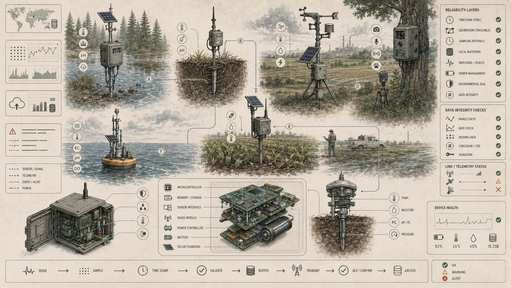
A practical embedded monitoring device architecture can be understood as a layered field evidence system. The exact implementation may involve electrochemical probes, optical sensors, pressure transducers, air-quality modules, soil probes, cameras, microphones, microcontrollers, embedded Linux boards, real-time clocks, local storage, cellular modems, LoRa radios, satellite telemetry, solar panels, enclosures, gaskets, mounts, desiccants, watchdogs, firmware manifests, QA/QC rules, and maintenance logs. The responsibilities remain consistent: sense, condition, sample, timestamp, store, check, protect, power, communicate, diagnose, maintain, and preserve meaning.
| Layer | Engineering Role | Primary Risk | Evidence Artifact |
|---|---|---|---|
| Observation objective layer | Defines the environmental variable, process, deployment duration, sampling cadence, decision use, and evidence standard. | Device design optimized for hardware convenience rather than monitoring purpose. | Device objective manifest, decision-use statement, deployment plan |
| Sensing layer | Converts environmental condition into electrical, optical, chemical, acoustic, mechanical, or digital signal. | Sensor drift, fouling, noise, interference, weak proxy relation, or poor placement. | Sensor specification, calibration record, observed-property definition |
| Signal conditioning and conversion layer | Amplifies, filters, digitizes, stabilizes, or normalizes the signal before logging. | Conversion artifacts, noise, ADC limits, temperature effects, undocumented filtering. | Signal-chain specification, ADC resolution, filter notes, firmware version |
| Control and timing layer | Schedules sampling, timestamps records, manages sleep/wake cycles, and coordinates device behavior. | Clock drift, missed samples, firmware instability, unlogged sampling-mode changes. | Firmware manifest, time-source record, sampling policy, device log |
| Power layer | Provides energy through batteries, solar, mains, harvesting, regulators, and power-management circuits. | Battery depletion, brownout, seasonal solar failure, power noise, unsafe duty cycle. | Power budget, voltage telemetry, charge log, energy model |
| Storage and buffer layer | Preserves raw or processed observations locally during routine operation and communications outages. | Storage corruption, capacity loss, overwritten records, unmarked delayed data. | Storage policy, buffer depth, retention rule, replay log |
| Telemetry layer | Transmits records, health status, alerts, or summaries through wired, cellular, LPWAN, radio, satellite, or local retrieval. | Packet loss, delayed transmission, high energy use, missing acknowledgments. | Connectivity manifest, transmission log, retry policy, delayed-record flag |
| Mechanical and environmental protection layer | Protects electronics while allowing valid environmental contact or exposure. | Ingress, corrosion, condensation, biofouling, thermal distortion, mounting failure. | Enclosure specification, ingress notes, service record, exposure assessment |
| Diagnostics and governance layer | Tracks device state, calibration, maintenance, firmware, quality flags, and public evidence status. | Silent failure or unreviewable data stream. | Health telemetry, QA/QC log, maintenance log, governance register |
This architecture makes clear that embedded monitoring is not just sensing. It is an integrated field system in which every layer affects whether the record remains interpretable as environmental evidence.
Implementation Pattern
A rigorous embedded monitoring implementation begins with the environmental process and the decision horizon, not the device catalog. The correct design depends on whether the system is monitoring flood stage, turbidity, dissolved oxygen, PM2.5, soil moisture, microclimate, camera events, acoustic activity, groundwater level, infrastructure flow, stormwater overflow, or equipment health. Each use case implies different requirements for sampling cadence, sensor warm-up, power budget, ruggedization, calibration, local storage, telemetry latency, diagnostics, and service interval.
| Artifact | Purpose | Suggested Format |
|---|---|---|
| Device objective manifest | Defines the monitored variable, process, deployment setting, sampling cadence, decision use, and evidence standard. | YAML, Markdown, architecture decision record |
| Device and sensor registry | Lists device IDs, sensors, observed properties, units, firmware, calibration status, location, and owner. | CSV, SQL table, asset registry |
| Power budget and duty-cycle plan | Documents energy sources, sampling frequency, sleep schedule, telemetry demand, and expected deployment life. | YAML, spreadsheet, engineering note |
| Firmware and local-rule manifest | Documents firmware version, sampling logic, local QC, threshold rules, adaptive behavior, and update history. | YAML, release notes, device manifest |
| Calibration and maintenance log | Tracks predeployment calibration, field checks, drift, fouling, service events, and postdeployment validation. | CSV, SQL table, field log |
| Storage and telemetry manifest | Defines local retention, buffer capacity, transmission schedule, retry policy, delayed-record flags, and retrieval rules. | YAML, device configuration, runbook |
| Enclosure and deployment record | Documents mechanical protection, ingress strategy, mounting, environmental exposure, and installation conditions. | Markdown, photo log, installation checklist |
| QA/QC and data-integrity policy | Defines range checks, spike checks, flatline checks, missing-data rules, clock checks, drift checks, and suspect-data handling. | YAML, QAPP, validation script |
| Device health and observability log | Tracks battery, storage, uptime, clock drift, telemetry, firmware, calibration, and error states. | CSV, SQL table, dashboard, telemetry stream |
| Governance and evidence log | Records device replacements, firmware changes, calibration decisions, public caveats, and review status. | CSV, SQL table, governance register |
The implementation goal is to make field evidence reconstructable. Users should be able to move from a data point back to the sensor, from the sensor back to calibration state, from calibration back to service history, from service history back to deployment conditions, and from the device record back to the environmental process being observed.
Research-Grade Framing: Embedded Devices as Edge Infrastructures of Environmental Knowledge
A research-grade understanding of embedded monitoring devices begins by treating them as edge infrastructures of environmental knowledge. They sit at the boundary where environmental condition is first transformed into timestamped digital record. That boundary is decisive because every design choice made there—sensor type, deployment position, sampling interval, warm-up cycle, local filtering, storage logic, trigger rule, battery budget, communication schedule, firmware behavior, and enclosure architecture—shapes what later appears as environmental reality.
This means embedded devices are not passive collectors. They are selective observers. A device configured for low-power sparse sampling reveals a different environment from one configured for high-frequency event capture. A threshold-triggered camera reveals a different temporal world from an interval-based imager. A logger that stores raw values locally without live telemetry supports a different decision horizon from one that transmits alerts immediately but only under certain conditions. A water-quality sonde with strong calibration history produces a different evidentiary object from one that continues logging after fouling. The same site can become a different observational object depending on how the device is designed.
Embedded monitoring therefore changes observability itself. The field device determines whether a process appears as a smooth trend, a threshold exceedance, a missing interval, a compressed summary, a proxy trace, a quality-flagged anomaly, or a silent absence. The edge device is where environmental complexity is first discretized, filtered, bounded, and converted into evidence. In that sense, embedded hardware design is also an epistemology of what counts as an environmental event.
| Limited Pattern | Stronger Pattern | Why the Shift Matters |
|---|---|---|
| Install a sensor | Design a field evidence system with power, timing, calibration, storage, telemetry, and diagnostics | Prevents sensor presence from being mistaken for trustworthy observation. |
| Collect data | Preserve values with device state, calibration status, quality flags, firmware version, and deployment context | Makes field records interpretable after the fact. |
| Maximize autonomy | Design autonomy with diagnosable failure, serviceability, and governance | Prevents unattended operation from becoming unattended uncertainty. |
| Optimize power only | Balance power, fidelity, event capture, telemetry, and evidence integrity | Prevents low-power operation from erasing the events the system was built to observe. |
| Transmit values | Transmit values, quality, device health, timing, and evidence status | Allows users to distinguish environmental anomaly from device anomaly. |
| Repair failures after discovery | Design failure modes that are observable before evidence quality collapses | Protects monitoring systems from quiet degradation. |
The central research question is not “Can this device measure a variable?” but “Can this field-resident system preserve enough context, reliability, and integrity for its measurements to become environmental evidence?”
Formal Model: Availability, Power, Calibration, Drift, and Field Data Integrity
A useful formal model separates availability, power readiness, calibration validity, storage integrity, telemetry completeness, timing reliability, and field data integrity. Let \(A_d\) represent device availability, \(P_r\) power readiness, \(C_v\) calibration validity, \(S_i\) storage integrity, \(T_c\) telemetry completeness, \(K_t\) timing consistency, \(Q_c\) quality-control readiness, and \(F_d\) field data integrity. The device record becomes trustworthy when these components remain strong together, not when one sensor specification looks impressive in isolation.
A_{\mathrm{device}} = \frac{T_{\mathrm{valid\ operation}}}{T_{\mathrm{deployment}}}
\]
Interpretation: Device availability measures how much of the deployment period the device operated in a valid measurement state.
C_{\mathrm{record}} = \frac{N_{\mathrm{valid\ records}}}{N_{\mathrm{expected\ records}}}
\]
Interpretation: Record completeness measures whether expected observations were actually captured, stored, and available for interpretation.
P_{\mathrm{margin}} = \frac{E_{\mathrm{available}} – E_{\mathrm{required}}}{E_{\mathrm{required}}}
\]
Interpretation: Power margin measures whether available energy exceeds the expected energy demand of sampling, processing, storage, and communications.
D_{\mathrm{drift}} = \left|x_{\mathrm{field}} – x_{\mathrm{reference}}\right|
\]
Interpretation: Drift can be approximated as the difference between a field measurement and a reference or comparison measurement under comparable conditions.
K_{\mathrm{time}} = 1 – \min\left(\frac{\Delta t_{\mathrm{clock}}}{\Delta t_{\mathrm{allowed}}}, 1\right)
\]
Interpretation: Timing consistency decreases as clock drift approaches or exceeds the allowed timing error for the monitoring purpose.
Q_{\mathrm{field\ evidence}} = w_1A_{\mathrm{device}} + w_2C_{\mathrm{record}} + w_3P_{\mathrm{margin}} + w_4C_{\mathrm{calibration}} + w_5K_{\mathrm{time}} + w_6Q_{\mathrm{qc}} + w_7H_{\mathrm{health}}
\]
Interpretation: Field evidence quality depends on availability, record completeness, power margin, calibration status, timing consistency, quality control, and device-health visibility.
This formal structure protects against a common error in field monitoring: judging a device only by nominal sensor accuracy. Field evidence quality is a systems property. It depends on whether the device remains alive, calibrated, synchronized, protected, and diagnosable while exposed to the environment it is supposed to observe.
What Are Embedded Monitoring Devices for Field Observation?
Embedded monitoring devices are self-contained or semi-autonomous field systems built around a sensing and control core. They typically combine one or more sensors with a microcontroller or embedded computer, timing and logging functions, local storage, power supply, communications interface, firmware logic, diagnostics, and a protective enclosure or deployment structure. Their purpose is to observe environmental conditions repeatedly in situ and preserve those observations with enough temporal continuity and technical integrity to support later interpretation or real-time action.
Such devices may include water-quality sondes and stream, reservoir, or groundwater loggers; air-sensor pods and distributed exposure-monitoring devices; soil-moisture, temperature, and root-zone sensing units; autonomous weather and microclimate stations; camera-based, image-triggered, or acoustic environmental devices; stormwater, flow, or infrastructure-linked monitoring nodes; and custom embedded platforms for ecological, hydrological, agricultural, atmospheric, coastal, or restoration monitoring.
The defining feature of embedded monitoring devices is local autonomy under field constraints. They are designed to continue sensing, timestamping, buffering, diagnosing, and sometimes interpreting or transmitting data without continuous human presence. That makes them more than instrument carriers. They are edge observing systems whose design determines how much of the environment can be captured between visits, beyond direct line of sight, or within narrow event windows that would otherwise go unobserved.
| Device Type | Observed Domain | Typical Signals | Integrity Concern |
|---|---|---|---|
| Water-quality sonde | Streams, reservoirs, groundwater, distribution systems | Temperature, conductivity, pH, dissolved oxygen, turbidity, nitrate, chlorophyll | Fouling, calibration drift, sensor replacement, flow exposure |
| Stage or pressure logger | Rivers, wetlands, stormwater, groundwater | Water level, pressure, stage, flow proxy | Datum control, sediment, debris, pressure drift, venting |
| Air-sensor pod | Urban air, wildfire smoke, community monitoring | PM2.5, PM10, gases, temperature, humidity | Humidity effects, calibration, placement, intended-use limits |
| Soil and root-zone node | Agriculture, restoration, ecology | Soil moisture, temperature, salinity, matric potential | Probe contact, soil disturbance, depth accuracy, freeze-thaw effects |
| Weather and microclimate station | Field climate, heat, evapotranspiration, fire weather | Temperature, humidity, wind, radiation, rainfall, pressure | Sensor siting, shielding, wind exposure, maintenance |
| Camera or acoustic node | Biodiversity, habitat, wildfire, surface condition | Images, video, sound, detections, activity windows | Storage, power, false detections, lens fouling, model confidence |
| Infrastructure-linked monitor | Stormwater, water systems, environmental infrastructure | Flow, pressure, vibration, pump state, overflow signal | Mechanical vibration, access, safety, telemetry, calibration |
Embedded devices are the material foundations of field observation. They translate environmental exposure into records, but their reliability depends on whether the whole device system—not only the sensing element—remains fit for the field.
Why Embedded Field Devices Matter
Embedded field devices matter because many environmental processes are intermittent, distributed, and temporally uneven in ways that manual observation alone cannot capture well. Flood pulses, contamination spikes, smoke episodes, dissolved-oxygen crashes, thermal inversions, habitat use, wet-weather overflows, groundwater responses, stormwater surges, wildlife activity, and equipment anomalies often occur between scheduled site visits and may disappear before conventional observation returns. Embedded devices reduce this temporal blindness by maintaining presence in the field.
They also matter because field observation is constrained by cost, remoteness, access, safety, labor availability, and institutional capacity. Mountain catchments, agricultural fields, estuaries, buried infrastructure, distribution assets, wetlands, restoration sites, underserved communities, and hazardous field environments all benefit from systems capable of operating for long periods with limited intervention. In such settings, embedded devices do more than automate measurement. They extend the spatial and temporal reach of observation into places and intervals that human sampling alone cannot sustain efficiently.
Most importantly, they matter because they alter the structure of evidence. A manually collected value is often a point in time. An embedded device can generate sequence, rhythm, variance, threshold crossing, event signature, failure trace, and recovery pattern. That means field phenomena become not only measurable, but reconstructable as processes. A system that persists can show whether a change was abrupt or gradual, isolated or repeated, rising or oscillating, real or instrumentally suspect. Embedded devices therefore matter because they shift environmental knowledge from episodic witness toward continuous or semi-continuous presence.
| Need | Embedded Device Contribution | Risk Without Embedded Field Devices |
|---|---|---|
| Temporal continuity | Captures sequences, events, cycles, and anomalies between field visits. | Environmental change is reduced to isolated snapshots. |
| Remote presence | Maintains observation where access is difficult, unsafe, or expensive. | Remote or hazardous sites remain under-observed. |
| Event capture | Records short-lived threshold crossings, pulses, anomalies, and activity windows. | Brief but consequential events are missed. |
| Operational awareness | Supports near-real-time status, alerts, and maintenance visibility. | Field conditions remain unknown until manual retrieval or delayed reporting. |
| Process reconstruction | Turns environmental values into time series and event histories. | Cause, timing, duration, and recovery are harder to infer. |
| Accountability | Creates durable evidence for monitoring programs, public reporting, and decision review. | Claims rely more heavily on sparse, anecdotal, or delayed observation. |
Embedded field devices matter because they extend observation into the time and place of environmental change. Their value is not merely automation. It is persistent, structured, edge-resident environmental witness.
Core Components of Embedded Monitoring Devices
Embedded field devices typically integrate several interdependent components. These are not optional accessories around sensing. They form one integrated measurement problem. A high-quality sensor without stable power is operationally weak. Robust telemetry without local buffering becomes brittle during outages. A rugged enclosure can preserve electronics while degrading thermal response, optical access, acoustic sensitivity, or chemical exchange if poorly designed. Embedded monitoring succeeds only when these layers are co-designed as one field system rather than assembled as a stack of disconnected parts.
| Component | Role | Failure Risk | Design Evidence |
|---|---|---|---|
| Sensing layer | Interacts with the environment through probes, transducers, optics, microphones, cameras, or chemical interfaces. | Drift, fouling, noise, interference, response lag, poor placement. | Sensor specification, calibration record, observed-property definition |
| Control and timing layer | Schedules sampling, manages local logic, timestamps records, and coordinates device behavior. | Clock drift, firmware fault, missed samples, unlogged mode changes. | Firmware manifest, sampling policy, time-source record |
| Power layer | Provides energy for sensing, processing, storage, telemetry, heating, or device recovery. | Battery depletion, brownout, solar underperformance, duty-cycle mismatch. | Power budget, battery telemetry, charging record |
| Storage layer | Retains raw or processed observations locally during normal operation and communications gaps. | Capacity overflow, corruption, overwrite, missing retrieval trace. | Storage manifest, retention policy, buffer status |
| Communications layer | Moves records, health telemetry, alerts, or summaries to receiving systems. | Packet loss, delayed data, high power draw, network outage. | Connectivity manifest, transmission log, acknowledgment record |
| Mechanical layer | Protects electronics while allowing valid environmental exposure. | Water ingress, condensation, corrosion, thermal distortion, biofouling, mounting failure. | Enclosure record, mounting specification, service notes |
| Diagnostics layer | Reports device health, power, storage, time, firmware, errors, and calibration status. | Silent degradation or inability to distinguish environment from device failure. | Health telemetry, error log, watchdog status |
| Governance layer | Maintains evidence integrity through maintenance, QA/QC, calibration, firmware control, and review. | Unreviewable data stream or unmanaged device lifecycle. | Maintenance log, QA/QC policy, governance register |
Embedded device design is therefore a full-stack discipline. It connects physical exposure, embedded control, environmental sensing, data integrity, telemetry, and institutional maintenance into one field evidence system.
Key Analytical Distinctions
A sensor is not the same as an embedded monitoring device. A sensor detects a variable; an embedded device manages time, power, storage, firmware behavior, protection, diagnostics, and often communication around that detection.
Device autonomy is not the same as device reliability. A device may sample and transmit without human presence while still failing through drift, fouling, enclosure breach, clock instability, storage corruption, or unnoticed firmware problems.
Data logging is not the same as remote monitoring. A device can record locally without providing timely visibility to operators. Remote awareness depends on telemetry, receiving systems, network reliability, and delayed-record handling.
Low power is not the same as field fitness. Power efficiency matters, but so do ruggedization, maintainability, calibration stability, environmental compatibility, recoverability, and graceful failure behavior.
Local processing is not the same as environmental understanding. Edge filtering, compression, thresholding, or classification can reduce bandwidth and trigger events, but interpretation still depends on context, metadata, validation, and downstream review.
Persistent presence is not the same as complete observability. Even long-duration embedded devices remain selective observers shaped by placement, variable choice, duty cycle, sensor physics, proxy limits, and service constraints.
| Distinction | Why It Matters | Design Implication |
|---|---|---|
| Sensor versus field evidence system | Measurement quality depends on the full device chain, not the sensor alone. | Document timing, power, storage, firmware, enclosure, diagnostics, and calibration. |
| Autonomy versus reliability | Unattended operation can hide degradation. | Track health telemetry, error states, drift indicators, and service intervals. |
| Persistence versus representativeness | Long duration at one site does not guarantee spatial or process representativeness. | Match device placement to monitoring objective and document site limitations. |
| Logging versus awareness | Locally stored data may be invisible during events. | Define telemetry strategy, retrieval schedule, and alert thresholds. |
| Power saving versus event capture | Low duty cycle can miss short-lived events. | Align sampling mode with process timescale and log adaptive changes. |
| Ruggedization versus measurement access | Protection can interfere with sensing if exposure is blocked or distorted. | Design enclosure and mounting around both survival and measurement fidelity. |
These distinctions prevent embedded monitoring from being reduced to device procurement. The field device is an evidentiary architecture, not merely hardware placed outdoors.
System Architecture: From Environmental Signal to Field Evidence
Embedded field devices operate as layered architectures that convert local environmental conditions into evidence-bearing data products. The value of an embedded device depends on the whole chain rather than on the sensing element alone. A sensor can be accurate while the logger clock drifts. A data stream can be clean while the enclosure slowly admits moisture. A trigger rule can conserve power while systematically missing the shortest and most important events. Embedded devices are therefore judged by whether they preserve end-to-end measurement integrity under field conditions.
| Stage | Transformation | Failure Risk |
|---|---|---|
| Physical environment | Environmental condition exists as water level, chemistry, particulate matter, temperature, moisture, sound, image, flow, or biological activity. | The selected variable may be only a partial proxy for the process of interest. |
| Signal capture | Sensing element responds to a physical, chemical, optical, thermal, acoustic, or biological condition. | Drift, fouling, placement error, exposure mismatch, response lag. |
| Conditioning and conversion | Electronics and firmware transform the signal into digital form. | Noise, ADC limits, filtering artifacts, undocumented correction. |
| Timestamping and logging | Measurements are recorded with time, device state, and contextual metadata where available. | Clock drift, missing timestamps, storage corruption, lost metadata. |
| Local management | Device schedules sleep cycles, sampling frequency, threshold behavior, storage, diagnostics, and power use. | Unlogged sampling-mode changes, brownout, watchdog resets, firmware faults. |
| Transmission or retrieval | Data are telemetered or collected during service intervals. | Packet loss, delayed records, missing acknowledgments, retrieval gaps. |
| QA/QC and interpretation | Downstream systems convert records into trends, alerts, event reconstructions, or decision-support evidence. | Device anomaly mistaken for environmental anomaly, weak calibration context. |
| Governance and review | Records are used in operational, scientific, public, or regulatory claims. | Claims exceed the evidentiary strength of the field device record. |
This architecture matters because every stage can preserve or weaken the evidentiary status of the final record. Embedded field data integrity is a chain property.
Sensors, Power, Logging, and Enclosure Design
The practical heart of embedded field observation lies in hardware integration. Sensors determine what environmental interaction is possible, but logging architecture determines how often it is sampled, how it is stored, and whether ancillary device state is preserved. Power design determines whether the system can survive through deployment intervals, seasonal variation, and communications demand. Enclosure design determines whether all of that remains physically viable once exposed to the actual environment.
Power is often the most unforgiving constraint because it governs duty cycle, sensor warm-up, local computation, heating, data retention, and telemetry frequency. Batteries set a temporal budget on observation. Solar systems can extend that budget, but only if light availability, orientation, shading, charge control, seasonal weather, and storage chemistry are aligned with the real deployment context. Power architecture is therefore not a secondary utility. It determines which measurement regime is even possible.
Enclosure design is equally decisive because embedded devices must survive while still sensing. They must resist water ingress, dust, insects, UV exposure, thermal swings, corrosion, biofouling, and mechanical shock, yet still allow the sensing interface to contact the medium of interest. This creates a fundamental design tension: enough openness to measure accurately, enough protection to survive long enough for the measurement to matter. Embedded field design is therefore always a negotiation between exposure and endurance.
| Design Dimension | Field Role | Failure Mode | Review Question |
|---|---|---|---|
| Sensor selection | Determines which environmental interaction can be measured. | Sensor unsuitable for range, medium, process, or intended use. | Does the sensor match the target variable and field conditions? |
| Sampling cadence | Determines temporal resolution and event capture. | Short events missed; battery exhausted by oversampling. | Does cadence match process timescale and power budget? |
| Power system | Sustains sensing, logging, processing, and telemetry. | Brownout, seasonal energy deficit, battery aging, regulator failure. | Is power margin adequate under worst-case deployment conditions? |
| Local storage | Preserves records through telemetry gaps or retrieval intervals. | Overflow, corruption, overwrite, missing retention trace. | Can storage survive outage and retrieval windows? |
| Telemetry hardware | Provides remote visibility and status updates. | Connectivity failure, high power demand, delayed records. | Does telemetry match geography, latency need, and energy budget? |
| Enclosure and mounting | Protects the device while maintaining measurement exposure. | Ingress, fouling, thermal distortion, corrosion, mechanical failure. | Does protection preserve measurement validity as well as device survival? |
| Diagnostics | Reveals device health and distinguishes system problems from environmental signals. | Silent degradation, unobserved resets, undiagnosed fault states. | Can operators see health, error, power, storage, and calibration status? |
Good embedded design is not about maximizing one specification. It is about making the whole field device coherent enough to persist, measure, and explain itself under real conditions.
Edge Processing, Storage, Telemetry, and Autonomy Tradeoffs
Embedded devices increasingly perform more work at the field edge. They may average or smooth readings, detect threshold exceedance, compress images, trigger local actuators, control duty cycles, flag suspect values, buffer event windows, or prioritize which data should be sent first. Edge processing can reduce bandwidth, extend battery life, improve event responsiveness, and enable monitoring in places where continuous telemetry is unrealistic. But it also pushes interpretive choices into the device itself.
Storage and telemetry create their own tradeoffs. A device with robust local storage can preserve high-resolution records through communications outages, but may delay response if data remain unseen until retrieval. A device optimized for near-real-time telemetry can support faster awareness, but often at the cost of higher power consumption and greater dependence on network continuity. In remote deployments, telemetry may be intermittent or expensive, which means designers must choose how to balance persistence, timeliness, and autonomy rather than maximizing all three simultaneously.
The deeper systems point is that edge processing is not just a technical convenience. It determines what counts as an event, what gets buffered or discarded, and what becomes visible to the rest of the monitoring system. Embedded devices therefore participate in interpretation before the data ever reach a model or dashboard. The field edge is not only where data are captured; it is where environmental reality is first filtered.
| Design Choice | Strength | Risk | Governance Requirement |
|---|---|---|---|
| Local thresholding | Supports low-latency event detection. | Threshold may be brittle across seasons or sites. | Rule version, threshold rationale, alert-review log |
| Adaptive sampling | Conserves power while capturing events at higher resolution. | Time series may become statistically uneven. | Sampling-mode log and trigger reason |
| Local compression | Reduces transmission and storage burden. | Raw signal structure may be lost. | Compression manifest and retained audit samples |
| Local buffering | Protects data during telemetry outage. | Buffer overflow or delayed-data confusion. | Buffer depth, replay log, delayed-record flag |
| Scheduled telemetry | Reduces energy demand and network cost. | Events may remain unseen until later. | Telemetry interval, priority channel, alert exception policy |
| Event-triggered telemetry | Provides timely awareness during important conditions. | Trigger logic can miss low-confidence or emerging events. | Trigger rule, confidence flag, missed-event review |
| Local inference | Enables preliminary classification or anomaly detection at the device. | Inferred labels may be mistaken for measured facts. | Model card, confidence score, inference label, retained context |
Embedded autonomy should be designed as controlled local responsibility. The more a device filters, classifies, triggers, or acts locally, the stronger the need for traceability and review.
Ruggedization, Exposure, and the Engineering of Persistence
Embedded field devices live in the very environments they are asked to measure, which means reliability is inseparable from exposure. Water loggers foul. Air sensors drift under humidity and thermal stress. Soil probes shift as soils swell, shrink, freeze, thaw, or are disturbed. Camera and imaging systems must balance weather sealing with optical access. Ports corrode. Connectors wick moisture. Condensation forms inside enclosures. Mounts loosen under wind, vibration, animals, vegetation growth, debris, or ice. A device that survives in the laboratory may fail quietly when placed in the field long enough to matter.
This is why laboratory performance and field performance must be kept analytically distinct. A device that behaves well under controlled testing may deteriorate quickly under sediment load, salt spray, smoke, mud, heat, UV exposure, chemical exposure, freeze-thaw cycles, or long unattended intervals. Reliability in embedded monitoring is therefore not an intrinsic property of a product alone. It is a function of deployment environment, mechanical design, service interval, installation quality, and fit between the device and the process it is meant to observe.
Exceptional embedded systems are designed for persistence rather than merely for startup success. They incorporate exposure-aware mounting, serviceable housings, diagnostic status channels, replaceable components, visible failure indicators, and failure modes that are detectable rather than silent. In harsh environments, graceful degradation and diagnosable failure can matter as much as nominal measurement accuracy.
| Exposure Risk | Typical Effect | Design Response | Evidence Artifact |
|---|---|---|---|
| Water ingress | Electronics failure, corrosion, condensation, intermittent faults. | Sealing, venting, desiccant, conformal coating, enclosure inspection. | Ingress inspection log, enclosure record |
| Biofouling | Sensor drift, optical blockage, chemical response distortion. | Wipers, anti-fouling materials, maintenance schedule, comparison checks. | Fouling inspection and cleaning log |
| Thermal stress | Sensor bias, battery degradation, enclosure condensation, electronics instability. | Thermal shielding, sensor compensation, component selection, ventilation. | Temperature telemetry, thermal design note |
| Corrosion and salt exposure | Connector failure, housing degradation, electrical leakage. | Marine-grade materials, sealed connectors, service checks. | Material specification, connector inspection |
| Sediment, debris, or ice | Blocked ports, altered flow exposure, physical damage. | Protective guards, placement review, service interval adjustment. | Deployment photo log, obstruction record |
| Animals, vandalism, or human disturbance | Dislodgement, theft, cable damage, changed orientation. | Mounting security, concealment, tamper indicators, site checks. | Tamper log, mounting inspection |
| Vibration and mechanical fatigue | Loose connectors, mounting failure, signal noise. | Strain relief, vibration-resistant mounts, periodic inspection. | Mounting record, vibration note |
Ruggedization is not cosmetic durability. It is part of measurement integrity because physical survival and valid environmental exposure must be designed together.
Calibration, QA/QC, and Field Data Integrity
Embedded field devices depend on QA/QC because unattended operation amplifies the risks of drift, fouling, clock error, state ambiguity, and silent malfunction. A field device must therefore support not only measurement but credibility. That credibility comes from calibration protocols, deployment records, maintenance logs, status diagnostics, metadata discipline, plausibility checks, comparison against references or neighboring instruments, and clear intended-use boundaries.
QA/QC begins before deployment with fit-for-purpose evaluation. It continues through installation, field checks, firmware stability, power verification, service intervals, retrieval, remote review, and postdeployment validation. Devices intended for regulatory, scientific, public-health, or early-warning use require especially careful treatment because plausible-looking but degraded data can be more damaging than obvious absence. Quality assurance should be tied to intended use rather than assuming one universal validation standard fits every deployment.
Field data integrity is a chain property. It depends on whether the path from environmental condition to logged number remains interpretable enough that the resulting record can support inference. Calibration is not a one-time predeployment ritual. It is part of the continuing life of the device and the evidentiary status of every value it produces.
| QA/QC Responsibility | Purpose | Evidence Artifact |
|---|---|---|
| Predeployment calibration | Establishes initial measurement validity and reference context. | Calibration certificate, calibration date, reference method |
| Deployment documentation | Preserves location, depth, height, orientation, exposure, mounting, and installation context. | Deployment record, GPS/location, photo log, site notes |
| Field checks | Detects drift, fouling, damage, enclosure issues, or placement changes. | Field inspection log, comparison measurement, service notes |
| Automated QC checks | Flags impossible values, spikes, flatlines, missing intervals, clock issues, or stale calibration. | Quality flags, suspect-data log, rule ID |
| Device-state capture | Distinguishes environmental change from device degradation. | Battery voltage, internal humidity, temperature, storage, reboot count |
| Timing integrity | Ensures records can be aligned with events, other sensors, weather, or external data. | Clock source, drift estimate, synchronization record |
| Postdeployment validation | Assesses whether records remain credible across the deployment period. | Post-retrieval check, drift assessment, final data-quality report |
Trustworthy embedded monitoring treats QA/QC as part of the device lifecycle. The strongest field systems make data quality visible while the device is deployed, not only after the archive is already compromised.
Quiet Failure, Blind Spots, and Operational Constraints
Embedded monitoring devices have distinctive failure modes, and many of the most consequential are quiet. Batteries deplete gradually. Solar charging underperforms seasonally. Sensors foul without crossing obvious alarm thresholds. Clocks drift subtly. Storage media degrade. Firmware faults cause intermittent loss. Communications links fail in patterns. Enclosures remain closed while internal humidity rises. Trigger logic misses the very events it was meant to capture. These are not dramatic breakdowns so much as creeping epistemic erosion.
Embedded devices also create blind spots by design. A single robust logger may be temporally rich but spatially unrepresentative. A low-power duty cycle may conserve battery while missing short-lived but consequential events. A device tuned to one variable may ignore a more causal variable for the same process. An autonomous imaging system may capture surface condition while missing chemistry, sound, subsurface dynamics, or social exposure. Embedded presence is therefore always selective presence, and that selectivity must be matched carefully to the monitoring objective.
Operational constraints further shape what is possible. Maintenance windows, site access, technician expertise, vandalism risk, spare-part availability, permitting, safety protocols, seasonal deployment conditions, and institutional support all affect whether a device remains useful over time. Embedded monitoring is therefore never just a hardware narrative. It is also a field operations narrative about what can be sustained in practice.
| Failure Mode | Consequence | Prevention or Detection |
|---|---|---|
| Battery decline | Reduced sampling, missed records, brownout resets, telemetry failure. | Battery telemetry, power budget review, low-power alert. |
| Solar underperformance | Seasonal energy deficit despite nominal renewable supply. | Charge logs, seasonal shading review, worst-case energy model. |
| Sensor fouling | Gradual bias or flatline values that still appear plausible. | Inspection, wipers, drift checks, neighboring/reference comparison. |
| Clock drift | Events cannot be aligned accurately across devices or external records. | Clock synchronization, drift estimate, time-source record. |
| Storage corruption or overflow | Record gaps, unrecoverable data, overwritten events. | Storage health telemetry, buffer policy, retrieval checks. |
| Enclosure breach | Condensation, corrosion, intermittent electronics failure. | Humidity sensor, enclosure inspection, desiccant review. |
| Firmware instability | Intermittent resets, changed sampling logic, silent mode changes. | Firmware manifest, watchdog log, reboot counter, release notes. |
| Telemetry dropout | Delayed awareness, stale dashboards, missing alerts. | Heartbeat checks, retry logs, delayed-record flags, store-and-forward buffer. |
Strong embedded monitoring systems are designed so that failure becomes visible before it becomes irreversible evidence loss. The goal is not perfect field operation. It is diagnosable, recoverable, and honestly bounded operation.
Maintainability, Standards, and Evidentiary Accountability
Embedded monitoring devices are part of governance infrastructures because they often feed larger observing systems, warnings, compliance workflows, scientific records, operational dashboards, and public evidence claims. Their design choices therefore affect more than local convenience. They shape what evidence enters shared systems and how credible that evidence remains when used in institutional decisions.
Maintainability matters especially here. A device that cannot be serviced predictably, documented clearly, or integrated into broader workflows may function technically while underperforming institutionally. Conversely, a simpler embedded system with stable protocols, well-managed metadata, clear calibration practice, and reliable serviceability can contribute more to long-term monitoring accountability than a more sophisticated but brittle platform. Standards matter for similar reasons: without common ways of describing device state, measurement context, quality, timing, and maintenance history, data become harder to compare, trust, and reuse.
In that sense, embedded field devices are not merely clever edge hardware. They are the field-level evidentiary foundations of larger monitoring claims. A trend line, alert, exposure estimate, or compliance decision may look abstract and centralized, but its credibility often begins with whether the embedded device at the edge was designed and maintained honestly enough to survive, measure, and report under real conditions.
| Governance Responsibility | Question | Evidence |
|---|---|---|
| Device stewardship | Who owns, maintains, replaces, calibrates, and retires each device? | Owner, asset registry, lifecycle log, service plan |
| Calibration governance | How are calibration status, drift, field checks, and postdeployment validation managed? | Calibration log, drift report, reference checks, QA/QC record |
| Firmware governance | Are firmware versions, local rules, and updates recorded? | Firmware manifest, release notes, update log |
| Metadata governance | Are device identity, observed property, unit, location, time, and quality status preserved? | Observation schema, required metadata fields, validation report |
| Maintenance governance | Are service intervals realistic for deployment conditions? | Maintenance schedule, field inspection log, service ticket |
| Data-integrity governance | Are gaps, suspect values, delayed records, and device faults visible to users? | Quality flags, gap report, delayed-record flag, device-health log |
| Public accountability | Can public-facing claims be traced back to field-device evidence? | Evidence package, caveats, method note, data-quality statement |
Governance is how embedded field observation remains trustworthy after devices leave the laboratory and become unattended witnesses in the world.
Future Directions
The future of embedded monitoring devices lies in deeper integration of low-power electronics, edge processing, ruggedized materials, adaptive duty cycles, self-diagnostics, flexible telemetry, open data models, and clearer device-state reporting. The most important advances are likely to come not only from smaller or cheaper sensors, but from more trustworthy edge systems that preserve measurement integrity longer in harsher conditions with less intervention.
Artificial intelligence and edge inference will expand the role of embedded devices through local anomaly detection, adaptive sampling, sensor-fault detection, preliminary classification, event-triggered imaging, acoustic filtering, and maintenance prediction. But these capabilities also increase the need for stronger device governance. If a field device classifies an event locally, its model version, confidence, input context, and retained audit sample should be visible. If it adapts sampling locally, the trigger and sampling-mode change should be logged. If it suppresses data locally, the retention and discard policy should be explicit.
The deeper challenge is not simply to make field devices smarter. It is to make them more interpretable, maintainable, and fit for purpose under real deployment constraints. Future systems will need stronger support for drift detection, fouling awareness, metadata capture, field-health telemetry, failure reporting, secure firmware update, and explicit alignment between device design and the kinds of environmental inference the monitoring program actually requires.
Environmental field conditions are rarely forgiving, and embedded devices are never complete observers. They are selective, power-limited, exposure-bound systems that make some parts of the world measurable by persisting where people cannot. Where they are well designed, they extend environmental knowledge into times, places, and event regimes that would otherwise remain poorly seen. Where they are weakly designed, autonomy can become a quiet producer of uncertainty rather than a cure for it. In that sense, embedded monitoring devices for field observation are infrastructures of edge visibility, selective autonomy, and evidentiary reliability.
Deployment Readiness Gate
Before an embedded monitoring device is deployed for public communication, environmental reporting, hazard alerting, infrastructure monitoring, ecological assessment, water-quality review, air-quality monitoring, sustainability strategy, or regulatory support, it should pass a deployment readiness gate. This gate should test whether the device is technically functional, field-ready, power-safe, calibrated, diagnosable, serviceable, and appropriate for its intended evidence use.
| Readiness Area | Required Question | Pass Evidence |
|---|---|---|
| Purpose readiness | Does the device match the environmental variable, process timescale, deployment duration, and decision use? | Device objective manifest, monitoring purpose, decision-use statement |
| Sensor readiness | Is the sensor appropriate for the range, medium, exposure, and intended use? | Sensor specification, range review, fit-for-purpose assessment |
| Calibration readiness | Is predeployment calibration current and documented? | Calibration record, calibration date, reference method, acceptance criteria |
| Power readiness | Can the device support sampling, processing, storage, telemetry, and diagnostics for the deployment interval? | Power budget, battery model, solar/charging record, duty-cycle plan |
| Timing readiness | Can the device preserve time accurately enough for event reconstruction and data integration? | Clock source, synchronization plan, drift tolerance |
| Storage readiness | Can local storage preserve expected records during normal operation and outages? | Storage capacity, retention policy, buffer and overwrite rules |
| Telemetry readiness | Does communication support required latency, completeness, and recovery? | Connectivity manifest, retry policy, delayed-record handling |
| Ruggedization readiness | Can the enclosure, mounting, and exposure strategy survive field conditions without distorting measurement? | Enclosure specification, mounting plan, exposure assessment, service checklist |
| Diagnostics readiness | Can operators distinguish environmental anomaly from device anomaly? | Health telemetry, error states, battery/storage status, calibration status |
| Governance readiness | Are maintenance, firmware, QA/QC, data integrity, public caveats, and review responsibilities defined? | Maintenance plan, firmware manifest, QA/QC policy, governance log |
This readiness gate prevents embedded devices from being deployed merely because they can measure in a test setting. The stronger standard is whether they can preserve trustworthy evidence under real field conditions.
Data and Configuration Artifacts
A reproducible embedded-device workflow should include explicit artifacts for device objectives, sensors, firmware, power, calibration, maintenance, storage, telemetry, enclosure design, QA/QC, device health, and governance. These artifacts make field-device evidence auditable rather than hidden inside hardware and field notes.
| Artifact | Purpose | Suggested Path |
|---|---|---|
| Device objective manifest | Defines monitored process, deployment setting, sampling cadence, decision use, and evidence standard. | config/device_objective.yml |
| Device and sensor registry | Lists device IDs, sensors, observed properties, units, calibration status, firmware, location, and owner. | data/device_sensor_registry.csv |
| Power budget manifest | Defines battery capacity, solar/charging assumptions, sampling demand, telemetry demand, and power margin. | config/power_budget.yml |
| Firmware and local-rule manifest | Documents firmware version, sampling logic, local QC, thresholds, adaptive behavior, and update history. | config/firmware_manifest.yml |
| Calibration and maintenance log | Tracks calibration, field checks, drift, fouling, service events, and postdeployment validation. | data/calibration_maintenance_log.csv |
| Device health telemetry sample | Stores battery, storage, internal humidity, temperature, reboot count, telemetry, and diagnostic status. | data/device_health_records.csv |
| Field observation schema | Defines required record fields for device identity, observed property, unit, time, quality, calibration, and device health. | schemas/field_observation.schema.json |
| QA/QC policy | Defines range, spike, flatline, missing-data, clock, drift, battery, and stale-calibration checks. | config/field_qaqc_policy.yml |
| Embedded readiness scores | Stores availability, record completeness, power margin, calibration validity, timing consistency, QC readiness, and device-health visibility. | data/embedded_device_readiness_scores.csv |
| Governance log | Records firmware updates, device replacements, calibration decisions, public caveats, and review status. | data/embedded_device_governance_log.csv |
These artifacts turn embedded field devices from isolated instruments into transparent and reproducible components of environmental evidence infrastructure.
Mathematical Lens: Field Availability, Data Integrity, Power, Drift, and Reliability
Several simple metrics can help evaluate embedded monitoring device readiness. These metrics are not substitutes for engineering review, calibration protocols, field judgment, or domain expertise, but they make field evidence quality more inspectable.
A_{\mathrm{device}} = \frac{T_{\mathrm{valid\ operation}}}{T_{\mathrm{deployment}}}
\]
Interpretation: Device availability measures the share of deployment time in which the device was operating in a valid measurement state.
C_{\mathrm{record}} = \frac{N_{\mathrm{valid\ records}}}{N_{\mathrm{expected\ records}}}
\]
Interpretation: Record completeness measures whether expected observations were captured, stored, and available for interpretation.
P_{\mathrm{margin}} = \frac{E_{\mathrm{available}} – E_{\mathrm{required}}}{E_{\mathrm{required}}}
\]
Interpretation: Power margin measures whether available energy exceeds the expected energy demand for sensing, processing, storage, diagnostics, and telemetry.
D_{\mathrm{drift}} = \left|x_{\mathrm{field}} – x_{\mathrm{reference}}\right|
\]
Interpretation: Drift can be approximated as the difference between a field measurement and reference or comparison value under comparable conditions.
K_{\mathrm{time}} = 1 – \min\left(\frac{\Delta t_{\mathrm{clock}}}{\Delta t_{\mathrm{allowed}}}, 1\right)
\]
Interpretation: Timing consistency decreases as clock drift approaches or exceeds the allowed timing error for the monitoring purpose.
Q_{\mathrm{field\ evidence}} = w_1A_{\mathrm{device}} + w_2C_{\mathrm{record}} + w_3P_{\mathrm{margin}} + w_4C_{\mathrm{calibration}} + w_5K_{\mathrm{time}} + w_6Q_{\mathrm{qc}} + w_7H_{\mathrm{health}}
\]
Interpretation: Field evidence quality depends on device availability, record completeness, power margin, calibration validity, timing consistency, QA/QC readiness, and health telemetry visibility.
These measures evaluate embedded devices as field evidence systems. They ask whether a device remains operational, complete, powered, calibrated, time-consistent, quality-controlled, and diagnosable.
Python Workflow: Embedded Device Readiness and Field Data Integrity
A Python workflow can demonstrate how embedded monitoring devices might be evaluated for availability, record completeness, power margin, calibration status, timing consistency, QA/QC readiness, health visibility, and decision fit. The purpose is not to create a universal score, but to make device-readiness dimensions visible.
from dataclasses import dataclass
from typing import List
import pandas as pd

@dataclass
class EmbeddedDevice:
    device_id: str
    domain: str
    device_type: str
    valid_operation_hours: float
    deployment_hours: float
    valid_records: int
    expected_records: int
    energy_available_wh: float
    energy_required_wh: float
    calibration_validity: float
    clock_drift_seconds: float
    allowed_clock_drift_seconds: float
    qc_readiness: float
    health_visibility: float
    decision_fit: float
    high_stakes_use: bool

def device_availability(device: EmbeddedDevice) -> float:
    if device.deployment_hours <= 0:
        return 0.0
    return max(0.0, min(1.0, device.valid_operation_hours / device.deployment_hours))

def record_completeness(device: EmbeddedDevice) -> float:
    if device.expected_records <= 0:
        return 0.0
    return max(0.0, min(1.0, device.valid_records / device.expected_records))

def power_margin_score(device: EmbeddedDevice) -> float:
    if device.energy_required_wh <= 0:
        return 0.0
    margin = (device.energy_available_wh - device.energy_required_wh) / device.energy_required_wh
    return max(0.0, min(1.0, 0.5 + margin))

def timing_consistency(device: EmbeddedDevice) -> float:
    if device.allowed_clock_drift_seconds <= 0:
        return 0.0
    ratio = abs(device.clock_drift_seconds) / device.allowed_clock_drift_seconds
    return max(0.0, 1.0 - min(ratio, 1.0))

def field_evidence_quality(device: EmbeddedDevice) -> float:
    return (
        0.16 * device_availability(device) +
        0.16 * record_completeness(device) +
        0.14 * power_margin_score(device) +
        0.16 * device.calibration_validity +
        0.12 * timing_consistency(device) +
        0.14 * device.qc_readiness +
        0.12 * device.health_visibility +
        0.10 * device.decision_fit
    )

def classify_review_priority(device: EmbeddedDevice, score: float) -> str:
    if device.high_stakes_use and device.calibration_validity < 0.80:
        return "high_stakes_calibration_review"
    if device_availability(device) < 0.75:
        return "device_availability_review"
    if record_completeness(device) < 0.80:
        return "record_completeness_review"
    if power_margin_score(device) < 0.50:
        return "power_budget_review"
    if timing_consistency(device) < 0.75:
        return "timing_integrity_review"
    if device.qc_readiness < 0.75:
        return "qaqc_readiness_review"
    if device.health_visibility < 0.75:
        return "device_health_visibility_review"
    if device.decision_fit < 0.75:
        return "decision_fit_review"
    if score < 0.75:
        return "field_evidence_quality_review"
    return "routine_monitoring"

devices: List[EmbeddedDevice] = [
    EmbeddedDevice(
        "river-stage-logger-001",
        "water",
        "pressure_stage_logger",
        690,
        720,
        2840,
        2880,
        140,
        112,
        0.92,
        3,
        10,
        0.88,
        0.84,
        0.90,
        True,
    ),
    EmbeddedDevice(
        "community-air-node-002",
        "air_quality",
        "pm_sensor_pod",
        610,
        720,
        2440,
        2880,
        95,
        110,
        0.74,
        12,
        10,
        0.78,
        0.82,
        0.84,
        True,
    ),
    EmbeddedDevice(
        "soil-moisture-node-003",
        "soil",
        "low_power_soil_node",
        700,
        720,
        1420,
        1440,
        55,
        48,
        0.86,
        5,
        30,
        0.76,
        0.72,
        0.78,
        False,
    ),
    EmbeddedDevice(
        "wetland-camera-trap-004",
        "biodiversity",
        "camera_trap",
        560,
        720,
        860,
        1440,
        180,
        150,
        0.82,
        20,
        60,
        0.70,
        0.68,
        0.74,
        False,
    ),
]

records = []
for device in devices:
    score = field_evidence_quality(device)
    records.append({
        "device_id": device.device_id,
        "domain": device.domain,
        "device_type": device.device_type,
        "device_availability": round(device_availability(device), 3),
        "record_completeness": round(record_completeness(device), 3),
        "power_margin_score": round(power_margin_score(device), 3),
        "calibration_validity": device.calibration_validity,
        "timing_consistency": round(timing_consistency(device), 3),
        "qc_readiness": device.qc_readiness,
        "health_visibility": device.health_visibility,
        "decision_fit": device.decision_fit,
        "field_evidence_quality": round(score, 3),
        "review_priority": classify_review_priority(device, score),
    })

df = pd.DataFrame(records)
print(df.sort_values(["review_priority", "field_evidence_quality"]))
This workflow treats embedded devices as field evidence systems. A device is not ready merely because it produces values. It must remain available, complete, powered, calibrated, time-consistent, quality-controlled, health-visible, and fit for its decision role.
R Workflow: Device Reliability, Calibration, and Field Operations Reporting
An R workflow can support embedded-device governance by summarizing readiness across device types, domains, calibration status, power margin, timing consistency, and review priorities. This is useful for field-program audits, deployment review, maintenance planning, and data-integrity reporting.
library(dplyr)
library(readr)

embedded_devices <- tribble(
  ~device_id, ~domain, ~device_type, ~valid_operation_hours, ~deployment_hours, ~valid_records, ~expected_records, ~energy_available_wh, ~energy_required_wh, ~calibration_validity, ~clock_drift_seconds, ~allowed_clock_drift_seconds, ~qc_readiness, ~health_visibility, ~decision_fit, ~high_stakes_use,
  "river-stage-logger-001", "water", "pressure_stage_logger", 690, 720, 2840, 2880, 140, 112, 0.92, 3, 10, 0.88, 0.84, 0.90, TRUE,
  "community-air-node-002", "air_quality", "pm_sensor_pod", 610, 720, 2440, 2880, 95, 110, 0.74, 12, 10, 0.78, 0.82, 0.84, TRUE,
  "soil-moisture-node-003", "soil", "low_power_soil_node", 700, 720, 1420, 1440, 55, 48, 0.86, 5, 30, 0.76, 0.72, 0.78, FALSE,
  "wetland-camera-trap-004", "biodiversity", "camera_trap", 560, 720, 860, 1440, 180, 150, 0.82, 20, 60, 0.70, 0.68, 0.74, FALSE
)

device_summary <- embedded_devices %>%
  mutate(
    device_availability = pmax(0, pmin(1, valid_operation_hours / deployment_hours)),
    record_completeness = pmax(0, pmin(1, valid_records / expected_records)),
    power_margin_score = pmax(0, pmin(1, 0.5 + ((energy_available_wh - energy_required_wh) / energy_required_wh))),
    timing_consistency = pmax(0, 1 - pmin(abs(clock_drift_seconds) / allowed_clock_drift_seconds, 1)),
    field_evidence_quality = round(
      0.16 * device_availability +
      0.16 * record_completeness +
      0.14 * power_margin_score +
      0.16 * calibration_validity +
      0.12 * timing_consistency +
      0.14 * qc_readiness +
      0.12 * health_visibility +
      0.10 * decision_fit,
      3
    ),
    review_priority = case_when(
      high_stakes_use & calibration_validity < 0.80 ~ "high_stakes_calibration_review",
      device_availability < 0.75 ~ "device_availability_review",
      record_completeness < 0.80 ~ "record_completeness_review",
      power_margin_score < 0.50 ~ "power_budget_review",
      timing_consistency < 0.75 ~ "timing_integrity_review",
      qc_readiness < 0.75 ~ "qaqc_readiness_review",
      health_visibility < 0.75 ~ "device_health_visibility_review",
      decision_fit < 0.75 ~ "decision_fit_review",
      field_evidence_quality < 0.75 ~ "field_evidence_quality_review", TRUE ~ "routine_monitoring" ) ) %>%
  arrange(review_priority, field_evidence_quality)

print(device_summary)

write_csv(
  device_summary,
  "outputs/embedded_device_readiness_summary.csv"
)
The R workflow emphasizes that device review should account for availability, record completeness, power margin, calibration validity, timing consistency, QA/QC readiness, health telemetry, and decision fit. These dimensions help prevent field devices from being judged by sensor specification alone.
Systems Code: Embedded Devices, Logging, Telemetry, Firmware, and Diagnostics
Embedded field monitoring depends on full-stack systems code. The stack includes firmware, device drivers, local data logging, real-time clocks, watchdogs, power management, storage buffers, telemetry protocols, device registries, quality-control flags, maintenance records, receiving APIs, health dashboards, and governance logs. A serious companion repository should therefore include both analytical workflows and systems-code scaffolding.
| Language / Tool | Role in Companion Repository | Example Use |
|---|---|---|
| Python | Device readiness scoring, field-data integrity review, calibration and health telemetry analysis | Embedded field evidence-quality scoring and review triage |
| R | Device reliability, calibration, and field operations reporting | Readiness summaries and maintenance dashboards |
| SQL | Device registry, calibration logs, device health records, field observations, governance logs | Auditable embedded monitoring database schema |
| C | Microcontroller-style observation record and threshold logic scaffold | Low-level environmental record construction |
| C++ | Local data logger, buffer, and event queue simulation | Store-and-forward and device event buffering |
| MicroPython | Low-power field-node example | Battery-aware sampling, local logging, threshold flags |
| Go | Lightweight device-health endpoint or ingestion service | Serve device status, calibration, battery, storage, and firmware metadata |
| Rust | Safe validation CLI for field observations and device manifests | Validate required observation and health fields |
| TypeScript | Dashboard and platform data models | Device cards, health panels, calibration status, field-data quality indicators |
| TinyML | On-device fault detection or event-classification placeholder | Sensor-fault detection, field event classification, confidence records |
| PYNQ / HDL | Streaming threshold, signal filtering, or device-health placeholders | Hardware-assisted local filtering and event detection |
This breadth is appropriate because embedded monitoring is not only a hardware problem. It is an evidence infrastructure problem spanning firmware, field mechanics, energy systems, logging, telemetry, QA/QC, observability, and governance.
GitHub Repository
A companion repository for this article should translate the embedded-device framework into reproducible technical scaffolding. The repository should include device objective manifests, device and sensor registries, power-budget models, firmware manifests, calibration and maintenance logs, field observation schemas, device-health telemetry examples, readiness scoring workflows, SQL schemas, embedded code examples, telemetry service examples, and governance logs.
Complete Code RepositoryThe companion repository provides reproducible examples for embedded monitoring devices in field observation, including device-readiness scoring, field-data integrity review, power-margin analysis, calibration and maintenance records, device-health telemetry, local logging, QA/QC flags, firmware manifests, and multi-language systems scaffolding for reliable environmental field devices.
Testing and Validation
Testing embedded monitoring devices requires more than confirming that sensors return values. It requires validating sensor suitability, calibration, timing, power margin, firmware behavior, storage, telemetry, enclosure performance, field deployment, diagnostics, QA/QC rules, maintenance procedures, and postdeployment data quality. A device can appear operational while producing weak evidence if any part of the field chain is untested or invisible.
| Test Type | Purpose | Example Test |
|---|---|---|
| Sensor suitability test | Ensure the sensing element fits the range, medium, process, and intended use. | Expose device to expected measurement range and deployment conditions. |
| Calibration test | Ensure predeployment and postdeployment calibration are documented. | Compare against reference standard before and after deployment. |
| Clock and timing test | Ensure timestamps remain accurate enough for event reconstruction. | Measure clock drift across deployment interval and temperature range. |
| Power-budget test | Ensure energy supply supports sensing, processing, storage, telemetry, and diagnostics. | Stress-test sampling and telemetry under worst-case energy assumptions. |
| Storage and buffer test | Ensure records survive communications outage and local storage limits. | Simulate outage and validate record retention, replay, and overflow behavior. |
| Firmware behavior test | Ensure sampling, sleep cycles, thresholds, watchdogs, and error handling behave as intended. | Run firmware through scripted operating states and fault injection. |
| Telemetry test | Ensure transmitted records arrive complete, timely, and correctly flagged. | Measure packet loss, latency, acknowledgments, and delayed-record labeling. |
| Enclosure and exposure test | Ensure protection does not compromise measurement validity. | Inspect ingress, condensation, mounting, fouling, thermal response, and sensor exposure. |
| QA/QC test | Ensure range, spike, flatline, missing-data, stale-calibration, and drift rules work. | Run synthetic and field records through QA/QC rules. |
| Postdeployment validation | Assess whether data remain credible after field exposure. | Review drift, gaps, calibration, battery, storage, firmware, and field notes together. |
Validation should test the embedded device as a chain of field evidence. The decisive question is not only whether the device can measure, but whether its measurements remain trustworthy after exposure, autonomy, delay, and field operations.
Operational Signals and Device Observability
Embedded monitoring devices must observe themselves. A device that monitors the environment but cannot report its own power, storage, firmware, clock, calibration, telemetry, enclosure condition, reboot state, or diagnostics is operationally fragile. Device observability should track both technical health and evidence health.
| Signal | Why It Matters | Failure Indicator |
|---|---|---|
| Device heartbeat | Determines whether the device is alive and reporting. | Missing heartbeat, repeated reboot, stale status. |
| Battery voltage and power state | Determines whether sampling and telemetry can continue. | Voltage decline, brownout reset, unexpected sleep mode. |
| Charge and solar status | Determines whether energy harvesting is meeting seasonal demand. | Low charge recovery, shaded panel, seasonal deficit. |
| Storage capacity | Determines whether records can be retained locally. | Near-full storage, overwritten files, failed writes. |
| Clock drift | Determines whether observations can be aligned with events and other records. | Time offset beyond allowed tolerance. |
| Calibration status | Determines whether measurements remain valid for intended use. | Expired calibration, drift signal, service overdue. |
| Internal humidity or enclosure status | Detects condensation, leak, or enclosure degradation. | Humidity rise, moisture indicator, enclosure alarm. |
| Firmware version and reboot count | Determines whether device behavior is stable and traceable. | Unexpected firmware version, repeated watchdog reset. |
| Telemetry latency and delivery | Determines whether remote awareness is timely and complete. | Delayed records, packet loss, missing acknowledgments. |
| QA/QC failure rate | Determines whether measurement quality is degrading. | Spike, flatline, range failure, missing-data surge. |
Operational observability protects embedded devices from quiet failure. It helps ensure that the appearance of field monitoring does not outlast the quality of the evidence chain beneath it.
Engineer and Researcher Checklist
- Define the environmental process, decision use, deployment duration, and evidence standard before selecting hardware.
- Match sensor type, range, response time, and exposure requirements to the monitored variable and field setting.
- Document device ID, sensor ID, firmware version, observed property, unit, location, deployment context, and owner.
- Build a power budget that accounts for sampling, sensor warm-up, processing, storage, telemetry, diagnostics, and worst-case field conditions.
- Preserve phenomenon time, result time, ingestion time, clock source, and timing-drift assumptions.
- Design local storage and buffering for communications outages, retrieval delays, and event windows.
- Use telemetry for both environmental values and device-health signals, not values alone.
- Document calibration status, field checks, maintenance events, drift indicators, and postdeployment validation.
- Design enclosures and mounts for both physical survival and measurement validity.
- Log firmware changes, local rules, sampling modes, watchdog resets, and error states.
- Use QA/QC flags for range, spike, flatline, missingness, stale calibration, timing drift, and device-health anomalies.
- Maintain governance records for device replacement, firmware update, calibration decisions, public caveats, and data-quality review.
Where This Fits in the Series
This article connects Environmental Monitoring Systems to edge computing, IoT architectures, environmental sensor networks, smart water systems, air-quality monitoring, weather sensing, river and watershed monitoring, data platforms, dashboards, and risk and resilience. It sits at the field-device layer of the series: the point where environmental observability becomes physically embedded in devices that must survive and measure under real-world conditions.
Within the broader series, this article provides the field-device framework that supports IoT architectures for environmental monitoring, edge computing in environmental monitoring, environmental sensor networks, smart water systems and environmental sensing, weather sensing and atmospheric data systems, river and watershed monitoring networks, environmental data platforms, and future environmental monitoring systems. Its role is to show that field observation is not merely a matter of placing sensors outdoors. It is a full-stack design problem around persistence, reliability, calibration, data integrity, and evidentiary accountability.
Related articles
- Edge Computing in Environmental Monitoring
- IoT Architectures for Environmental Monitoring
- Environmental Sensor Networks
- Smart Water Systems and Environmental Sensing
- Weather Sensing and Atmospheric Data Systems
- River and Watershed Monitoring Networks
- Remote Sensing Systems in Environmental Monitoring
- Environmental Data Platforms and Decision Support Systems
- Monitoring Environmental Risk and Resilience
- Environmental Monitoring Systems
Further reading
- U.S. Environmental Protection Agency (2026) Water Sensors Toolbox. Available at: https://www.epa.gov/water-research/water-sensors-toolbox
- U.S. Environmental Protection Agency (2026) Water Sensors Presentations and Publications. Available at: https://www.epa.gov/water-research/water-sensors-presentations-and-publications
- U.S. Environmental Protection Agency (2018) Online Water Quality Monitoring in Distribution Systems for Water Quality Surveillance and Response Systems. Available at: https://www.epa.gov/sites/default/files/2018-05/documents/owqm-ds_guidance_042018.pdf
- U.S. Environmental Protection Agency (2026) Quality Assurance for Air Sensors. Available at: https://www.epa.gov/air-sensor-toolbox/quality-assurance-air-sensors
- U.S. Environmental Protection Agency (2026) Air Sensor Toolbox. Available at: https://www.epa.gov/air-sensor-toolbox
- U.S. Geological Survey (2026) Hydrologic Instrumentation Facility. Available at: https://www.usgs.gov/labs/hydrologic-instrumentation-facility
- U.S. Geological Survey (2026) Instrumentation Evaluations. Available at: https://www.usgs.gov/labs/hydrologic-instrumentation-facility/instrumentation-evaluations
- U.S. Geological Survey (2026) Instrumentation Services. Available at: https://www.usgs.gov/labs/hydrologic-instrumentation-facility/instrumentation-services
- U.S. Geological Survey (2026) An Automated Digital Imaging System for Environmental Monitoring Applications. Available at: https://www.usgs.gov/publications/automated-digital-imaging-system-environmental-monitoring-applications
- National Oceanic and Atmospheric Administration, Integrated Ocean Observing System (2026) QARTOD. Available at: https://ioos.noaa.gov/project/qartod/
- National Oceanic and Atmospheric Administration, Integrated Ocean Observing System (2022) QARTOD Project Plan Update 2022–2026. Available at: https://cdn.ioos.noaa.gov/media/2022/05/QARTOD-Project-Plan-Update-2022-2026_Final.pdf
- National Oceanic and Atmospheric Administration, Integrated Ocean Observing System (2026) Access IOOS Data. Available at: https://ioos.noaa.gov/data/access-ioos-data/
References
- National Oceanic and Atmospheric Administration, Integrated Ocean Observing System (2022) QARTOD Project Plan Update 2022–2026. Available at: https://cdn.ioos.noaa.gov/media/2022/05/QARTOD-Project-Plan-Update-2022-2026_Final.pdf (Accessed: 14 May 2026).
- National Oceanic and Atmospheric Administration, Integrated Ocean Observing System (2026) Access IOOS Data. Available at: https://ioos.noaa.gov/data/access-ioos-data/ (Accessed: 14 May 2026).
- National Oceanic and Atmospheric Administration, Integrated Ocean Observing System (2026) QARTOD. Available at: https://ioos.noaa.gov/project/qartod/ (Accessed: 14 May 2026).
- U.S. Environmental Protection Agency (2018) Online Water Quality Monitoring in Distribution Systems for Water Quality Surveillance and Response Systems. Available at: https://www.epa.gov/sites/default/files/2018-05/documents/owqm-ds_guidance_042018.pdf (Accessed: 14 May 2026).
- U.S. Environmental Protection Agency (2026) Air Sensor Toolbox. Available at: https://www.epa.gov/air-sensor-toolbox (Accessed: 14 May 2026).
- U.S. Environmental Protection Agency (2026) Quality Assurance for Air Sensors. Available at: https://www.epa.gov/air-sensor-toolbox/quality-assurance-air-sensors (Accessed: 14 May 2026).
- U.S. Environmental Protection Agency (2026) Water Sensors Presentations and Publications. Available at: https://www.epa.gov/water-research/water-sensors-presentations-and-publications (Accessed: 14 May 2026).
- U.S. Environmental Protection Agency (2026) Water Sensors Toolbox. Available at: https://www.epa.gov/water-research/water-sensors-toolbox (Accessed: 14 May 2026).
- U.S. Geological Survey (2026) An Automated Digital Imaging System for Environmental Monitoring Applications. Available at: https://www.usgs.gov/publications/automated-digital-imaging-system-environmental-monitoring-applications (Accessed: 14 May 2026).
- U.S. Geological Survey (2026) Hydrologic Instrumentation Facility. Available at: https://www.usgs.gov/labs/hydrologic-instrumentation-facility (Accessed: 14 May 2026).
- U.S. Geological Survey (2026) Instrumentation Evaluations. Available at: https://www.usgs.gov/labs/hydrologic-instrumentation-facility/instrumentation-evaluations (Accessed: 14 May 2026).
- U.S. Geological Survey (2026) Instrumentation Services. Available at: https://www.usgs.gov/labs/hydrologic-instrumentation-facility/instrumentation-services (Accessed: 14 May 2026).