
Last Updated August 6, 2026
Electricity grids are among the largest continuously coordinated technical systems ever built. They connect generators, transmission lines, substations, transformers, distribution networks, storage, industrial facilities, buildings, data centers, transportation systems, public infrastructure, and millions of individual devices. Unlike many commodity networks, electricity systems must keep production and consumption closely balanced through time while also maintaining voltage, frequency, equipment limits, and network security.
A grid is therefore more than wires carrying electricity from power plants to consumers. It is a real-time physical and institutional coordination system. Power flows according to electrical laws rather than contractual intentions. Generators and loads interact through a common network. Operators continuously monitor conditions, dispatch resources, maintain reserves, manage congestion, coordinate outages, respond to faults, and prepare for disturbances that can propagate across large regions.
Modern electricity grids are also changing rapidly. Wind and solar generation, batteries, electric vehicles, heat pumps, data centers, distributed energy resources, advanced power electronics, digital control, and new transmission are altering both supply and demand. These changes do not eliminate the fundamental requirements of grid operation. They change how those requirements are satisfied.
This article introduces the physical and operational foundations of electricity grids: generation, transmission, distribution, balancing, frequency, voltage, power flow, substations, transformers, reserves, system control, storage, inverter-based resources, interconnection, and planning. It establishes the technical foundation for the next article, Grid Reliability and Resilience.
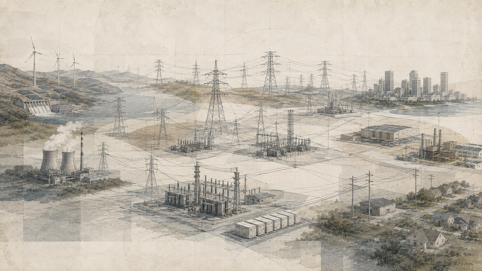
A useful way to understand the grid is to separate its physical layers from its operational functions. The physical network moves electrical energy. The operational system monitors, forecasts, schedules, dispatches, protects, and restores that network. Markets and regulation allocate responsibilities, costs, revenues, and investment incentives around the same physical system.
What Is an Electricity Grid?
An electricity grid is an interconnected network that transports electrical energy from sources of generation to end users while continuously coordinating supply, demand, and network conditions.
The word grid can describe several scales:
- a local distribution network serving a neighborhood or industrial facility;
- a utility system serving a city or region;
- a large synchronous interconnection spanning multiple states or countries;
- an islanded microgrid capable of operating independently;
- a national or multinational electricity system linked through high-voltage transmission.
The defining feature is interconnection. Once generators and loads share a network, their behavior becomes coupled. A change in one location can alter flows, frequency, voltage, loading, or reserves elsewhere.
Electricity is also unusual because large power systems generally have limited inherent storage relative to total throughput. Batteries, pumped storage, thermal storage, reservoirs, and other technologies can shift energy through time, but the grid as a whole still requires continuous balance between injections and withdrawals.
At every moment, operators must ensure that enough electrical power is being produced or released from storage to match consumption, storage charging, network losses, and exports while remaining within equipment and stability limits.
Grid Architecture: Generation to End Use
A simplified grid contains five physical layers:
| Layer | Primary function | Examples |
|---|---|---|
| Generation | Convert primary or stored energy into electricity | Thermal plants, hydropower, nuclear, wind, solar, geothermal, batteries discharging |
| High-voltage transmission | Move large quantities of power over long distances | Extra-high-voltage lines, high-voltage direct-current links, transmission substations |
| Subtransmission | Connect bulk transmission to regional load centers | Regional lines and substations at intermediate voltages |
| Distribution | Deliver power to local customers and distributed resources | Feeders, transformers, switches, service lines |
| End use and distributed resources | Consume, generate, store, or control electricity locally | Buildings, motors, data centers, EV chargers, rooftop solar, batteries, demand response |
The actual architecture is more networked than this linear sequence suggests. Large industrial customers may connect directly to transmission. Distributed solar can inject electricity from the distribution system toward upstream substations. Batteries can alternate between load and generation. Microgrids can disconnect from the larger system. High-voltage direct-current links can connect otherwise asynchronous systems.
The grid has therefore evolved from a largely one-directional architecture toward a more bidirectional and digitally controlled network.
Alternating Current and Interconnection
Most large power systems use alternating current, or AC, because voltage can be efficiently transformed between levels and because synchronous AC networks allow many generators and loads to operate together.
In an ideal sinusoidal AC system, voltage varies through time approximately as:
v(t)=V_{\mathrm{max}}\sin(2\pi f t+\phi)
\]
The waveform is characterized by amplitude, frequency \(f\), and phase angle \(\phi\).
Power systems operate at a nominal frequency, commonly 50 or 60 hertz depending on the system. Frequency is not merely a label on equipment. In a synchronous grid it reflects the collective balance between mechanical or electrical energy supplied to the system and electrical demand.
Large synchronous interconnections contain many rotating machines whose electromagnetic fields remain synchronized with the common waveform. Increasingly, inverter-based resources connect through power electronics rather than direct electromechanical synchronization, but they must still interact correctly with the grid’s frequency, voltage, and protection requirements.
High-voltage direct current, or HVDC, is also important. HVDC can move large quantities of power over long distances, connect asynchronous AC systems, control flows precisely, and support submarine transmission. It does not replace AC everywhere; it complements AC networks where its characteristics are valuable.
Three-Phase Power
Bulk electricity systems commonly use three-phase AC power. Three sinusoidal voltages are offset by 120 electrical degrees.
Three-phase systems are advantageous because they deliver nearly constant total power to balanced loads, use conductors efficiently, and work well with rotating electrical machines.
For a balanced three-phase system, active power can be approximated as:
P=\sqrt{3}V_L I_L \cos\phi
\]
Here \(V_L\) is line-to-line voltage, \(I_L\) is line current, and \(\cos\phi\) is power factor.
This relationship helps explain why utilities transmit power at high voltage. For a given amount of power, increasing voltage reduces the current required. Lower current reduces resistive losses and conductor heating.
Transformers and Voltage Levels
Transformers allow AC voltage to be stepped up or down efficiently.
Power is generally generated at moderate voltage, stepped up for transmission, then progressively reduced through substations and distribution transformers before reaching customers.
For an ideal transformer:
\frac{V_1}{V_2}=\frac{N_1}{N_2}
\]
Voltage ratio follows the ratio of turns on the transformer’s windings.
Ignoring losses, power is approximately conserved:
V_1 I_1 \approx V_2 I_2
\]
Stepping voltage upward therefore reduces current for the same power transfer.
Voltage levels vary by region and utility, so labels such as “transmission” and “distribution” describe function more reliably than one universal voltage threshold. The system is hierarchical because different voltage levels balance insulation cost, line capacity, equipment design, safety, and customer needs.
Transmission Systems
Transmission systems move bulk electricity between generators, regions, and major load centers.
A transmission network includes:
- high-voltage overhead and underground lines;
- substations;
- transformers;
- circuit breakers;
- reactive-power equipment;
- protection systems;
- communications and control;
- HVDC converters and links where used.
Transmission provides several forms of value. It allows low-cost generation to reach distant loads, shares reserves across regions, connects diverse resources, reduces the need for every locality to be self-sufficient, and provides alternative paths when equipment is unavailable.
But transmission also creates interdependence. Disturbances can propagate across interconnected areas if protection, operations, and system design do not contain them.
Transmission capacity is not simply a fixed number printed on a line. Usable transfer depends on thermal ratings, voltage performance, stability, outage conditions, network topology, ambient conditions, and system security criteria.
Substations and Switching
Substations are critical nodes where voltage is transformed, circuits are connected, power flows are switched, faults are isolated, and measurements are collected.
Typical substation equipment includes:
- power transformers;
- busbars;
- circuit breakers;
- disconnect switches;
- instrument transformers;
- protective relays;
- capacitors and reactors;
- communications systems;
- station batteries and control power.
Substation configuration affects reliability. A simple bus arrangement may be inexpensive but expose more equipment to a single fault. More redundant designs can isolate failures while keeping other circuits energized.
Switching also changes network topology. Opening or closing a breaker changes which electrical paths are available, which can redistribute power flows across a wide region.
Distribution Systems
Distribution networks deliver electricity from substations to local customers.
Traditional distribution systems were designed primarily for one-way flow: substation to feeder, feeder to transformer, transformer to customer. Distributed generation, batteries, electric vehicles, and controllable loads increasingly make flows bidirectional.
Distribution systems include:
- primary feeders;
- secondary networks;
- pole-mounted and pad-mounted transformers;
- voltage regulators;
- capacitor banks;
- switches and reclosers;
- meters;
- protective devices;
- communications and automation.
Local constraints can become important even when the bulk power system has sufficient generation. A neighborhood with rapid electric-vehicle adoption may overload a transformer. Rooftop solar may create high midday voltage on a feeder. Heat pumps may increase winter peak demand. Data centers may require new substations even if regional annual energy consumption remains manageable.
Distribution planning must therefore consider location and timing, not only annual consumption.
Real-Time Power Balance
The grid must maintain a continuously changing balance:
P_{\mathrm{generation}}
+P_{\mathrm{imports}}
+P_{\mathrm{storage\ discharge}}
=
P_{\mathrm{load}}
+P_{\mathrm{exports}}
+P_{\mathrm{storage\ charge}}
+P_{\mathrm{losses}}
\]
This is an instantaneous power relationship, not simply an annual energy balance.
A region may have enough annual energy generation but still face a shortage during a peak hour. Conversely, it may have excess generation during low-demand periods that must be exported, curtailed, stored, or shifted through demand response.
Operators therefore manage megawatts through time. Energy planning in megawatt-hours is necessary but not sufficient.
Forecast error, plant outages, changing weather, variable renewable output, and unexpected demand continuously disturb the balance. Automatic controls and operating reserves correct these deviations.
Frequency and System Balance
In a synchronous AC grid, frequency is a system-wide indicator of short-term power balance.
If electrical demand suddenly exceeds supply, rotating machines begin to slow and frequency falls. If supply exceeds demand, they accelerate and frequency rises.
A simplified dynamic relationship is:
\Delta P=P_{\mathrm{mechanical}}-P_{\mathrm{electrical}}
\]
A power imbalance changes the kinetic energy stored in rotating equipment and therefore system frequency.
Traditional synchronous generators contribute physical inertia. Inverter-based resources do not inherently contribute inertia in the same electromechanical way, although appropriately controlled inverters can provide fast frequency response and other grid-support functions.
Frequency control occurs at several layers:
- inertial or very fast response immediately after a disturbance;
- primary frequency response from governors or fast controls;
- automatic generation control restoring scheduled balance;
- manual redispatch and reserve replacement over longer intervals.
The exact implementation differs among systems, but the physical requirement remains: active-power imbalance must be corrected quickly enough to keep frequency within acceptable bounds.
Voltage and Reactive Power
Voltage is a local and regional condition rather than a single system-wide variable like frequency in a synchronous interconnection.
Maintaining voltage requires controlling reactive power, transformer taps, generator excitation, inverter controls, capacitors, reactors, and other devices.
Long transmission lines, heavily loaded corridors, motors, transformers, and power-electronic equipment all affect reactive-power requirements.
Insufficient reactive support can cause voltage to decline. Excess reactive power can raise voltage. Severe voltage instability can contribute to cascading failure.
Voltage control is therefore both an operational and planning problem. It must be managed throughout transmission and distribution networks.
Active, Reactive, and Apparent Power
AC power is commonly described using three related quantities.
Active power, measured in watts, performs net work or transfers energy to loads.
Reactive power, measured in volt-amperes reactive, oscillates between electrical and magnetic fields and supports voltage in AC systems.
Apparent power, measured in volt-amperes, combines both.
For sinusoidal conditions:
S^2=P^2+Q^2
\]
where:
- \(S\) = apparent power;
- \(P\) = active power;
- \(Q\) = reactive power.
Power factor is:
\mathrm{PF}=\frac{P}{S}
\]
Low power factor means more current is required to deliver a given amount of active power, increasing equipment loading and losses.
How Power Flows Through a Network
Electricity does not follow contracts, company boundaries, or a single chosen route. In an interconnected AC network, power distributes across available paths according to impedance, voltage magnitudes, and phase-angle differences.
For a simplified lossless connection between two buses, active power transfer can be approximated as:
P\approx\frac{V_1V_2}{X}\sin(\delta)
\]
Power transfer increases with voltage magnitude and phase-angle difference and decreases with line reactance \(X\).
This equation captures an important principle: operators cannot instruct AC power to use only one transmission line while ignoring parallel paths. Network topology determines how flows distribute.
This creates loop flows and shared constraints across neighboring systems. A transaction between two areas can change loading on a third area’s transmission facilities.
Power-flow studies therefore model the network as a connected electrical system rather than a set of independent pipelines.
Thermal, Voltage, and Stability Limits
Transmission capacity is constrained by several types of limits.
Thermal limits arise because current heats conductors and equipment. Excess heating can damage equipment or cause overhead lines to sag dangerously.
Voltage limits ensure buses remain within acceptable operating ranges and adequate reactive-power margins exist.
Stability limits ensure the interconnected system remains synchronized and controllable after disturbances.
Protection limits ensure faults can be detected and isolated correctly.
Contingency limits preserve acceptable operation after specified equipment outages.
The binding constraint can change with weather, topology, generation dispatch, outages, and load. A line that can physically carry more current in cool weather may still be limited by system stability or contingency requirements.
Balancing Areas and Control Regions
Large grids are organized into operational areas responsible for maintaining balance within coordinated rules.
A balancing authority or equivalent operator typically:
- forecasts demand;
- schedules generation and interchange;
- monitors real-time system conditions;
- deploys balancing resources;
- maintains operating reserves;
- coordinates with neighboring systems;
- responds to contingencies.
Interchange schedules define planned transfers between areas, while actual flows reflect the physical network. Operators continuously correct deviations between schedules, load, and generation.
Regional coordination reduces the need for each area to balance in complete isolation. Diversity in load, weather, resources, and outages can provide substantial system value when transmission allows sharing.
Generation Dispatch
Dispatch determines which resources produce power and at what level.
In a simplified economic dispatch problem, operators minimize total operating cost subject to meeting demand and respecting generator and network constraints:
\min \sum_i C_i(P_i)
\]
subject to:
\sum_i P_i=P_{\mathrm{load}}+P_{\mathrm{losses}}
\]
and constraints such as:
- minimum and maximum output;
- ramp rates;
- startup and shutdown requirements;
- minimum run times;
- fuel availability;
- transmission constraints;
- reserve requirements;
- environmental limits.
Modern dispatch can also include storage state of charge, demand response, renewable forecasts, and security constraints.
The lowest marginal-cost generator cannot always serve the next increment of demand if transmission is constrained or if operational flexibility is needed elsewhere.
Operating Reserves and Flexibility
The grid must prepare for uncertainty and sudden events.
Operating reserves provide response beyond scheduled generation.
Reserve categories vary by system, but the underlying needs include:
- responding rapidly to a generator or transmission outage;
- correcting forecast error;
- following load and renewable variability;
- restoring reserves after deployment;
- maintaining sufficient upward and downward flexibility.
Resources providing flexibility can include:
- part-loaded generators;
- hydropower;
- batteries;
- demand response;
- imports;
- fast-start generation;
- controllable distributed resources.
A system with enough total capacity can still be operationally inflexible if resources cannot change output fast enough or remain available during critical periods.
Load Curves, Peaks, and Net Load
Electricity demand changes by hour, day, season, weather, and economic activity.
A load curve shows demand through time. The highest value is peak demand. Planning must ensure the system can serve not merely average demand but critical peaks under realistic outage and weather conditions.
Variable generation changes the concept from gross load to net load:
P_{\mathrm{net\ load}}
=
P_{\mathrm{gross\ load}}
-P_{\mathrm{variable\ generation}}
\]
A region with large solar capacity may have low net load at midday and a steep upward ramp in the evening as solar production falls while demand remains high.
This means annual renewable generation share alone does not describe operational challenge. The timing and correlation of generation with demand matter.
Load flexibility can reshape this relationship. Electric-vehicle charging, water heating, thermal storage, industrial loads, batteries, and building controls can move consumption away from constrained periods.
Transmission Constraints and Congestion
Congestion occurs when the unconstrained pattern of generation and demand would violate transmission limits.
Operators then redispatch resources: reducing output on one side of a constraint and increasing output elsewhere.
Congestion can create several consequences:
- higher operating cost;
- renewable curtailment;
- locational differences in electricity prices;
- greater use of local generation;
- delayed interconnection of new resources;
- incentives for transmission, storage, or demand flexibility.
A region may have abundant low-cost generation that cannot reach load because transmission is insufficient. Building more generation behind the same constraint may have little system value until network capacity expands.
Congestion therefore links generation planning with transmission planning.
Electrical Losses
Electricity networks lose energy through resistance and other physical processes.
For a conductor, resistive power loss is:
P_{\mathrm{loss}}=I^2R
\]
Because loss increases with the square of current, high-voltage transmission substantially reduces losses for a given power transfer.
Losses also occur in:
- transformers;
- cables;
- substations;
- power electronics;
- distribution equipment.
System losses vary with loading. A network operating near peak current can experience disproportionately greater losses than the same network under moderate loading.
Loss reduction can therefore come from higher voltage, improved conductors, efficient transformers, reactive-power management, distributed generation near load, reduced congestion, and better network design.
Energy Storage on the Grid
Storage decouples electricity generation from consumption across time.
A storage system can:
- charge during low-price or high-generation periods;
- discharge during peaks;
- provide frequency response;
- provide reserves;
- reduce renewable curtailment;
- support transmission or distribution constraints;
- provide backup power;
- support black start in some configurations.
Storage is characterized by both power and energy capacity.
A 100 MW battery can change power rapidly, but the number of hours it can sustain that output depends on stored energy. A 100 MW / 400 MWh battery can theoretically discharge at rated power for four hours before accounting for operating limits and efficiency.
Round-trip efficiency is:
\eta_{\mathrm{RT}}
=
\frac{E_{\mathrm{discharged}}}{E_{\mathrm{charged}}}
\]
Storage therefore shifts and reshapes energy; it does not create energy.
Distributed Energy Resources
Distributed energy resources, or DERs, are smaller resources connected primarily to distribution systems or behind customer meters.
They can include:
- rooftop and community solar;
- batteries;
- backup generation;
- electric vehicles;
- smart thermostats;
- controllable water heating;
- small combined heat and power systems;
- flexible industrial or commercial loads.
DERs can reduce bulk-system demand, provide local flexibility, and improve resilience. They can also create new challenges involving voltage, reverse flow, protection coordination, communications, cybersecurity, aggregation, and compensation.
The operational value of a DER depends strongly on location and timing. One megawatt of flexibility in a constrained feeder may have more local value than the same amount elsewhere.
Inverter-Based Resources
Solar photovoltaics, many wind turbines, batteries, and some modern loads connect to the grid through power electronics.
These inverter-based resources differ from directly synchronized rotating machines.
An inverter can control electrical output rapidly, but its behavior depends on software, measurement, control algorithms, hardware limits, and grid conditions.
Two broad control concepts are often distinguished:
- Grid-following controls, which synchronize to an existing voltage waveform.
- Grid-forming controls, which can establish or regulate voltage and frequency references under appropriate conditions.
Inverter-based resources can provide active power, reactive power, voltage support, fast frequency response, and other services if designed and operated to do so.
As their share grows, system planners must ensure the grid retains adequate frequency response, voltage control, fault behavior, protection performance, and stability.
The transition is therefore not simply from one generator type to another. It is also a transition in the physical control architecture of the power system.
Grid Interconnection
A new generator, storage facility, major load, or transmission project cannot simply connect to the grid without analysis.
Interconnection studies evaluate whether the project causes unacceptable conditions and which upgrades are required.
Studies may examine:
- thermal overloads;
- voltage performance;
- short-circuit levels;
- protection requirements;
- transient stability;
- steady-state power flow;
- network upgrades;
- control and communications requirements.
The interconnection problem becomes more complex when many projects enter queues simultaneously. Each project can affect the network upgrades needed by others.
Interconnection therefore sits at the boundary between private project development and shared public infrastructure.
Grid Operations Across Time Scales
Grid coordination occurs across many time scales.
| Time scale | Representative functions |
|---|---|
| Milliseconds to seconds | Protection, fault clearing, inverter controls, inertial or very fast response |
| Seconds to minutes | Primary frequency response, automatic generation control, fast reserves |
| Minutes to hours | Redispatch, storage scheduling, load following, congestion management |
| Day ahead | Commitment, generation schedules, interchange, reserve planning |
| Weeks to seasons | Maintenance scheduling, hydro planning, fuel inventories, seasonal adequacy |
| Years | Transmission expansion, generation investment, retirements, resource planning |
| Decades | Grid architecture, electrification, climate adaptation, regional development |
A resource can be valuable at one time scale and insufficient at another. A battery may respond within milliseconds but lack energy for a multi-day shortage. A thermal plant may sustain output for days but require hours to start. Transmission can share resources across geography but takes years to build.
Grid design therefore requires a portfolio of capabilities rather than one universal technology.
Protection, Automation, and Control
Power systems must detect faults and isolate damaged equipment quickly.
Protective relays monitor current, voltage, frequency, impedance, differential conditions, and other signals. Circuit breakers interrupt fault current. Reclosers can automatically restore service after temporary distribution faults. Supervisory control and data acquisition systems provide operators with measurements and remote control.
Protection must be selective. The objective is to isolate the smallest practical portion of the system while preserving service elsewhere.
Protection becomes more challenging as network conditions change. Distributed generation can alter fault current direction and magnitude. Inverter-based resources may provide different fault-current characteristics than synchronous machines. Changing topology alters coordination requirements.
Automation improves speed, but it also increases dependence on communications, software, cybersecurity, time synchronization, and data quality.
Black Start and System Restoration
If a large part of the grid loses power, restoration cannot assume that normal electricity supply is available to start every generator.
A black-start resource can initiate operation without relying on the external grid. It can energize local equipment and help start additional generation.
Restoration is staged because operators must manage:
- generator startup requirements;
- transformer energization;
- voltage control;
- frequency stability;
- load pickup;
- island synchronization;
- transmission paths;
- communications and staffing.
Restoring too much load too quickly can destabilize a small electrical island. Restoration plans therefore build the system progressively.
Batteries and inverter-based resources may provide new restoration options, but black-start capability depends on system-specific controls, energy availability, network conditions, and tested procedures.
Markets, Utilities, and System Operators
Electricity grids are physical systems governed by institutional arrangements.
Depending on jurisdiction, responsibilities can be divided among:
- vertically integrated utilities;
- transmission owners;
- distribution utilities;
- independent system operators;
- regional transmission organizations;
- generation companies;
- retail suppliers;
- regulators;
- municipal utilities;
- cooperatives;
- public power agencies.
Markets can coordinate energy, capacity, reserves, congestion, and ancillary services. Regulated systems can perform similar physical functions through administrative planning and dispatch.
The institutional form changes who bears risk, how investment is financed, how costs are recovered, and how operational decisions are made. It does not change Kirchhoff’s laws, frequency balance, transformer physics, or thermal limits.
This distinction is fundamental: market design operates around a physical network that must remain secure regardless of commercial arrangements.
Grid Planning and Expansion
Grid planning determines what infrastructure must exist years or decades before real-time operators need it.
Planning questions include:
- How much demand will exist?
- Where will new load appear?
- Which generators will retire?
- Where will new resources connect?
- How much transmission is needed?
- What storage duration is valuable?
- Which distribution feeders require reinforcement?
- How will extreme weather change demand and equipment ratings?
- Which contingencies must the system withstand?
Planning models combine load forecasts, generation portfolios, transmission topology, production cost, reliability requirements, engineering studies, environmental constraints, and economic assumptions.
Long-lived infrastructure creates path dependence. A transmission line built today may shape generation and development for decades. Delaying infrastructure can also create lock-in by forcing continued reliance on existing plants or local generation.
Planning is therefore an exercise in managing uncertainty under long asset lives.
Decarbonization and Electrification
Decarbonization changes both the generation mix and the architecture of demand.
Electrification of transportation, heating, and industry can increase electricity demand while reducing direct combustion of fuels. At the same time, wind and solar may shift generation toward different locations and weather-dependent patterns.
These changes can require:
- new transmission corridors;
- distribution upgrades;
- larger transformer capacity;
- more flexible demand;
- storage;
- new reserve strategies;
- advanced inverter controls;
- expanded regional coordination;
- better forecasting and digital monitoring.
Electrification can also create flexibility. Vehicles are parked much of the time. Buildings contain thermal mass. Water heaters can shift operation. Industrial processes may have scheduling flexibility. Properly coordinated demand can reduce the need for peak infrastructure.
The grid of the future is therefore not simply larger. It is likely to be more dynamic, more digitally controlled, more bidirectional, and more tightly coupled to transportation, buildings, industry, communications, and data systems.
Worked Examples
Example 1: Current Reduction at Higher Voltage
Suppose a three-phase line transfers 100 MW at unity power factor.
At 115 kV:
I=\frac{100\times10^6}{\sqrt{3}(115\times10^3)}\approx502\ \mathrm{A}
\]
At 230 kV:
I=\frac{100\times10^6}{\sqrt{3}(230\times10^3)}\approx251\ \mathrm{A}
\]
Doubling voltage approximately halves current. Because resistive loss varies with \(I^2\), the same conductor resistance would experience approximately one-quarter of the loss.
Example 2: Power Balance
A region has:
- 8,200 MW generation;
- 400 MW imports;
- 250 MW battery discharge;
- 8,300 MW customer load;
- 300 MW exports;
- 120 MW network losses.
Supply is:
8200+400+250=8850\ \mathrm{MW}
\]
Demand plus losses and exports is:
8300+300+120=8720\ \mathrm{MW}
\]
There is a 130 MW surplus. Operators must reduce generation, increase storage charging, increase exports, or increase controllable demand to restore balance.
Example 3: Battery Duration
A battery is rated at 200 MW and 800 MWh.
Its nominal duration is:
T=\frac{800\ \mathrm{MWh}}{200\ \mathrm{MW}}=4\ \mathrm{hours}
\]
If only 90 percent of the stored energy is available within operating limits, usable energy is 720 MWh and full-power duration becomes 3.6 hours.
Example 4: Distribution Transformer Peak
A neighborhood transformer normally peaks at 400 kW. Twenty-five electric vehicles begin charging at 7.2 kW each during the evening peak.
Additional demand is:
25(7.2)=180\ \mathrm{kW}
\]
New coincident peak is approximately 580 kW if all chargers operate simultaneously.
Managed charging can shift part of that load to later hours and potentially defer a transformer upgrade.
Example 5: Net Load Ramp
At 4 p.m., gross load is 20 GW and solar output is 8 GW. Net load is 12 GW.
At 8 p.m., gross load is 22 GW and solar output is 0.5 GW. Net load is 21.5 GW.
The four-hour net-load increase is:
21.5-12=9.5\ \mathrm{GW}
\]
Average ramp requirement is:
\frac{9.5}{4}=2.375\ \mathrm{GW/h}
\]
The system must provide that increase through dispatchable generation, storage discharge, imports, demand reduction, or some combination.
Common Misconceptions
Misconception 1: Electricity travels along the contractual path chosen by the buyer and seller.
In an AC network, physical flows distribute across available paths according to network physics.
Misconception 2: Annual electricity generation proves the grid can meet demand.
Adequacy and operations depend on hourly timing, outages, ramps, reserves, transmission, and weather.
Misconception 3: Transmission lines have one fixed capacity.
Usable transfer depends on thermal, voltage, stability, contingency, topology, and environmental conditions.
Misconception 4: Frequency and voltage are the same kind of control problem.
Frequency largely reflects system-wide active-power balance in a synchronous grid; voltage is strongly local and linked to reactive power and network conditions.
Misconception 5: Storage creates electricity.
Storage shifts electricity through time and loses some energy in the process.
Misconception 6: Distribution is simply a smaller transmission system.
Distribution has different topology, protection, customer interfaces, voltage-control practices, and increasingly large numbers of distributed resources.
Misconception 7: A low-cost generator always runs first.
Transmission constraints, ramp limits, reserves, startup conditions, reliability requirements, and other constraints can change dispatch.
Python Workflow: Load, Generation, and Storage Balance
A simple time-series model can calculate hourly balance, curtailment, shortages, and battery state of charge.
from dataclasses import dataclass

@dataclass
class Battery:
    power_mw: float
    energy_mwh: float
    soc_mwh: float
    efficiency: float = 0.92


def step(load, generation, battery, hours=1.0):
    net = generation - load

    if net >= 0:
        # Charge from surplus generation.
        charge_input = min(
            net,
            battery.power_mw,
            (battery.energy_mwh - battery.soc_mwh)
            / (battery.efficiency * hours),
        )
        battery.soc_mwh += (
            charge_input * battery.efficiency * hours
        )
        curtailment = net - charge_input
        shortage = 0.0

    else:
        # Discharge to cover a deficit.
        required = -net
        discharge = min(
            required,
            battery.power_mw,
            battery.soc_mwh * battery.efficiency / hours,
        )
        battery.soc_mwh -= (
            discharge / battery.efficiency * hours
        )
        shortage = required - discharge
        curtailment = 0.0

    return {
        "soc_mwh": battery.soc_mwh,
        "curtailment_mw": curtailment,
        "shortage_mw": shortage,
    }

battery = Battery(
    power_mw=200,
    energy_mwh=800,
    soc_mwh=400,
)

load = [500, 520, 600, 700, 680]
generation = [650, 620, 550, 500, 720]

for hour, (demand, supply) in enumerate(
    zip(load, generation), start=1
):
    result = step(demand, supply, battery)
    print(hour, result)
A publication-grade grid workflow can add:
- multiple generators;
- ramp limits;
- reserve requirements;
- transmission constraints;
- renewable forecasts;
- storage degradation;
- imports and exports;
- load shedding;
- nodal power flow;
- contingency analysis.
The objective is not to reproduce a production system operator with a few lines of code. It is to make the physical balance and operational constraints explicit.
R Workflow: Transmission and Peak-Demand Scenarios
R can compare how demand growth and transmission capacity affect a simplified regional balance.
scenarios <- data.frame(
  scenario = c(
    "Current system",
    "Electrification",
    "Electrification + transmission",
    "Managed demand"
  ),
  peak_load_mw = c(10000, 12500, 12500, 11500),
  local_capacity_mw = c(8500, 9000, 9000, 9000),
  import_limit_mw = c(2000, 2000, 4000, 2500)
)

scenarios$available_mw <-
  scenarios$local_capacity_mw +
  scenarios$import_limit_mw

scenarios$margin_mw <-
  scenarios$available_mw -
  scenarios$peak_load_mw

print(scenarios)
This simplified comparison shows that higher demand does not automatically require equal growth in local generation. Transmission and demand flexibility can also contribute. But a real adequacy study must account for outages, weather dependence, correlated conditions, reserve requirements, deliverability, and resource availability during critical periods.
GitHub Repository
Complete Code Repository
The full Energy Systems repository contains reproducible article workflows, grid-balance models, load and generation time series, storage simulations, transmission examples, validation tools, datasets, documentation, and multi-language computational assets.
A Practical Grid-Analysis Method
A structured grid study can follow a repeatable sequence:
- Define the question. Is the problem energy supply, peak capacity, congestion, voltage, reliability, interconnection, storage, or expansion?
- Set the boundary. Identify buses, feeders, balancing areas, neighboring systems, generation, storage, and loads.
- Choose the time resolution. Annual energy, hourly dispatch, minute-level balancing, or subsecond dynamics answer different questions.
- Map network topology. Document lines, transformers, substations, voltage levels, and interfaces.
- Characterize generation. Include capacity, availability, marginal cost, ramp rate, startup behavior, and energy constraints.
- Characterize demand. Use load shape, peak demand, weather sensitivity, location, and flexibility.
- Represent storage. Include power, energy, state of charge, efficiency, and operating limits.
- Close the power balance. Require generation, imports, and discharge to equal load, exports, charging, and losses.
- Model network constraints. Test thermal, voltage, and transfer limits.
- Add reserves. Preserve enough flexibility for uncertainty and contingencies.
- Test outages. Examine credible equipment failures and maintenance states.
- Evaluate congestion. Identify where transmission changes dispatch or curtails resources.
- Test alternatives. Compare generation, transmission, storage, demand response, and distributed resources.
- Quantify uncertainty. Vary load, weather, outages, renewable output, fuel availability, and project timing.
- Connect to public outcomes. Report cost, reliability, emissions, access, land, resilience, and distributional effects.
A rigorous analysis should make clear whether each result is an energy result, a capacity result, a network result, or a reliability result. These quantities are related but not interchangeable.
Policy, Equity, and Public Value
Electricity grids are public-value systems because modern societies depend on them for essential services.
Grid decisions affect:
- electricity affordability;
- industrial competitiveness;
- public health;
- housing costs;
- transportation electrification;
- data infrastructure;
- economic development;
- emissions;
- land use;
- community resilience.
Infrastructure costs are also distributed unevenly. A transmission project may deliver regional benefits while crossing specific communities. Distribution upgrades may be driven by new high-income technology adoption but recovered broadly through rates. Customers with rooftop solar and batteries may reduce grid purchases while still depending on network services. Low-income households may have less ability to invest in flexible technologies or absorb high peak prices.
A public-value framework should ask:
- Who causes the need for investment?
- Who receives the benefit?
- Who pays?
- Who bears environmental and land-use burdens?
- Which customers are most vulnerable to outages?
- Which services must remain available during emergencies?
- How transparent are planning and interconnection decisions?
Grid engineering cannot answer these questions alone, but grid planning cannot responsibly ignore them.
Limits, Uncertainty, and Responsible Interpretation
Electricity grids are complex enough that simplified models can become misleading if their scope is not stated clearly.
Major sources of uncertainty include:
- future demand growth;
- weather;
- renewable output;
- equipment outages;
- fuel supply;
- project delays;
- load flexibility;
- storage performance;
- transmission expansion;
- technology cost;
- policy and market design;
- extreme events.
Model type also matters.
An annual energy model cannot determine whether frequency remains stable after a generator trip. A production-cost model may represent hourly dispatch but not detailed electromagnetic transients. A steady-state power-flow model can identify loading and voltage conditions but not necessarily dynamic stability. A distribution hosting-capacity study answers different questions from a resource-adequacy model.
Responsible analysis should match the model to the decision.
Results should also avoid false precision. A forecast showing peak demand of 12,347 MW ten years in the future may imply more certainty than the underlying assumptions justify. Scenario ranges and sensitivity analysis are often more useful.
The grid should be understood as a hierarchy of models and operational processes rather than one universal calculation.
Why the Grid Is a Coordinated System
Electricity grids transform geographically dispersed generation and demand into one coordinated electrical system.
Their central requirement is continuous balance. Generation, imports, and storage discharge must match load, exports, charging, and losses closely enough to maintain frequency. Voltage must remain within acceptable ranges. Reactive power must be managed. Transmission and distribution equipment must remain within thermal and stability limits. Protection must isolate faults quickly. Operators must maintain reserves and coordinate across regions.
The physical grid is therefore inseparable from control and institutions. Power-flow equations determine how electricity moves. Dispatch determines which resources operate. Market and regulatory rules influence investment and operating incentives. Planning determines which lines, substations, generators, and storage systems will exist years before real-time operators need them.
Decarbonization and electrification increase the importance of this coordination. Wind, solar, batteries, electric vehicles, heat pumps, data centers, distributed resources, and inverter-based generation change where power is produced, when it is consumed, and how the network behaves. They also create new opportunities for flexibility and control.
Understanding the grid requires moving between energy and power, annual planning and subsecond response, local equipment and regional networks, physics and institutions.
The next article, Grid Reliability and Resilience, builds on this foundation by examining resource adequacy, outage risk, operating security, extreme weather, redundancy, restoration, and the ability of electricity systems to withstand and recover from disturbance.
Related Articles
- Energy Systems Thinking
- Grid Reliability and Resilience
- Transmission and Distribution Systems
- Smart Grids
- Microgrids and Distributed Energy Systems
- Power-System Operations and Dispatch
- Grid Interconnection and Transmission Planning
- Energy Storage
Further Reading
- Kundur, Prabha. Power System Stability and Control.
- Grainger, John J., and William D. Stevenson Jr. Power System Analysis.
- Glover, J. Duncan, Thomas Overbye, and Mulukutla S. Sarma. Power System Analysis and Design.
- North American Electric Reliability Corporation. Reliability standards, assessments, and technical resources.
- U.S. Department of Energy. Grid modernization and transmission resources.
- National Renewable Energy Laboratory. Power-system integration, transmission, storage, and inverter research.
- International Energy Agency. Electricity grids, power systems, and energy-transition analysis.
References
- Kundur, Prabha. Power System Stability and Control. McGraw-Hill.
- Grainger, John J., and William D. Stevenson Jr. Power System Analysis. McGraw-Hill.
- Glover, J. Duncan, Thomas Overbye, and Mulukutla S. Sarma. Power System Analysis and Design. Cengage.
- North American Electric Reliability Corporation. Reliability and bulk-power-system resources. Available at: NERC.
- U.S. Department of Energy, Grid Deployment Office. Grid and transmission resources. Available at: DOE.
- National Renewable Energy Laboratory. Grid modernization and power-system research. Available at: NREL.
- International Energy Agency. Electricity grids and power-system analysis. Available at: IEA.
- Institute of Electrical and Electronics Engineers. Power and Energy Society standards and technical literature.